Tracker and SAS Placement
Topcon Paver System Five Operator’s Manual
6-10
immediately to the tow point movement, so the tracker
continues to send raise correct signals to the valve. By the time
the screed gets to grade (approximately 3 tow arm lengths), the
tow point cylinder has moved too far, causing the screed to
continue raising. The tracker senses this over correction and
sends a lower signal to the tow point cylinder, repeating the
whole process in the other direction. Therefore, with the tracker
mounted at the screed pivot point, long waves in the mat will be
produced because there is no feedback from the tow point
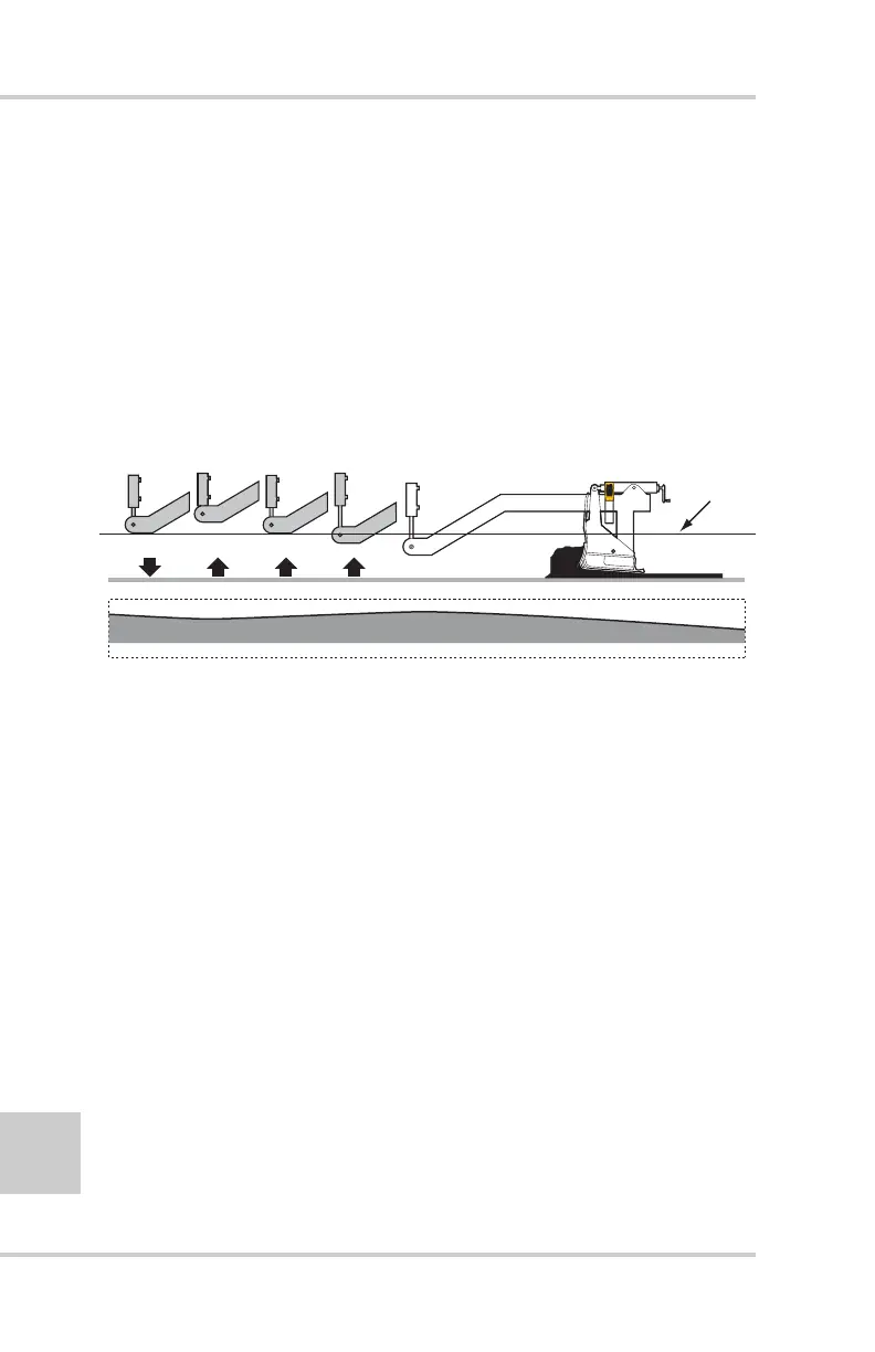
cylinder to the screed (Figure 6-12).
Figure 6-12. Tracker at Screed Pivot Point Causes Erroneous Corrections
• Example 2: Tracker Placed Incorrectly at Tow Point
At this point, where grade corrections are being made, the sonic
tracker is kept at an exact distance from the grade reference
(Figure 6-13 on page 6-11). Any tracker elevation changes will
cause the tow point cylinder to move immediately. The problem
with the tracker placed here is the lack of feedback from the
screed.
S
onic
T
racker
II
Reference
Average profile of mat with Sonic Tracker
TM
mounted at Screed