Operation & Menu Settings
Topcon Paver System Five Operator’s Manual
4-2
Control Box
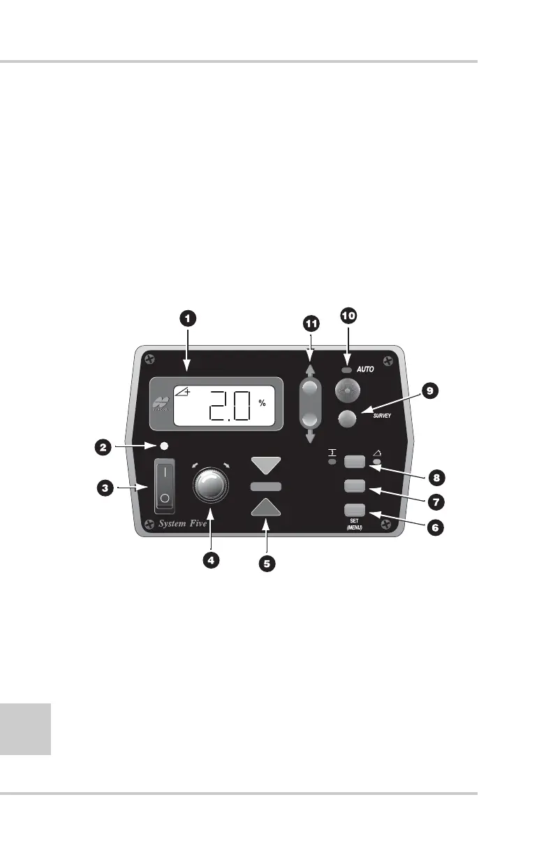
The Control Box is the operator’s interface to System Five™
(Figure 4-1), receiving signals from the sensors, and using these
signals to determine if grade or slope corrections are necessary. If
the paving requires a change in grade or slope, the Control Box
sends a signal to the valve controlling the tow point cylinder on the
appropriate side of the paver to raise or lower, thus maintaining
correct mat thickness. The operator can control and monitor the
slope and thickness of the mat using the buttons and displays
located on the front panel of the Control Box.
Figure 4-1. 9256 Control Box
1. LCD
2. Light Sensor for LED Display
3. Power Switch
4. Grade Adjustment Knob
5. Grade Adjustment LED
6. Set (Menu) Button
7. Cross Communication Button
8. Slope/Elevation Button
9. Survey Button
10. Auto/Manual Button
11. Jog Button