Getting Acquainted
P/N 7010-0341 www.topconpositioning.com
1-3
Getting Acquainted
A standard System Five Paver system includes two Control Boxes,
two Sonic Trackers and a single Slope Sensor. When setup and
connected, the Control Boxes control either the left or right side of
the machine for either elevation or slope.
Control Box
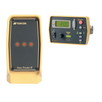
The Control Box (Figure 1-3) is the operator’s interface to
System Five. The Control Box receives signals from the sensors
(Sonic Tracker II™, Laser Tracker, and/or Slope Sensor), and
uses these signals to determine if grade or slope corrections are
necessary. If a change in grade or slope is required, the Control
Box sends a signal to the valve controlling the tow point
cylinder on the appropriate side of the machine to raise or
lower, thus maintaining correct mat thickness.
The Control Box connects to the Sonic Tracker II™, the Slope
Sensor, and to the paver through electrical cables. The Control
Box easily attaches to its mounting bracket with one clamp, and
at the end of the day should be removed for storage.
Figure 1-3. Control Box
AU
TO
S
UR
VEY
SET
(
M
E
NU
)
S
ystem
F
ive

 Loading...