Control Box Setup for Elevation
P/N 7010-0341 www.topconpositioning.com
5-7
Once one of the Trackers has been eliminated from the averaging,
the balance point of the beam will have changed. If the faulty
Tracker is not replaced the beam will need to be repositioned to
adjust for the new balance point. It is strongly recommended, if the
first or last Tracker fails, to replace it with one of the Trackers from
the middle of the beam. This will insure that the balance point is not
outside of the 1/3 to 2/3 rule.
NOTICE
NOTICE
A number reading of “1” could mean the first or
last Tracker has failed depending on which side
of the paver the beam has been mounted. The
SAS cable is labeled with numbers at each
connector for easy identification.
Control Box Setup for Elevation
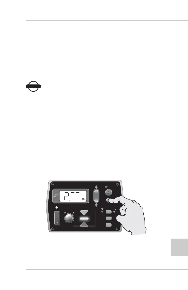
Once the Sonic Tracker has been positioned over the reference, the
Control Box can now set the tracker on-grade.
1. With the power on, press and hold the Survey button for one
second until the box beeps and the green on-grade bar lights up
(Figure 5-6).
Figure 5-6. Setting the Tracker On-grade
FiveSystem
AU
TO
S
UR
VEY
SET
(M
E
NU
)