EasyManuals Logo

Topcon Paver System 5 User Manual

Topcon Paver System 5
204 pages
To Next Page IconTo Next Page
To Previous Page IconTo Previous Page
Page #71 background imageLoading...
Page #71 background image
Control Box
P/N 7010-0341 www.topconpositioning.com
4-3
LCD
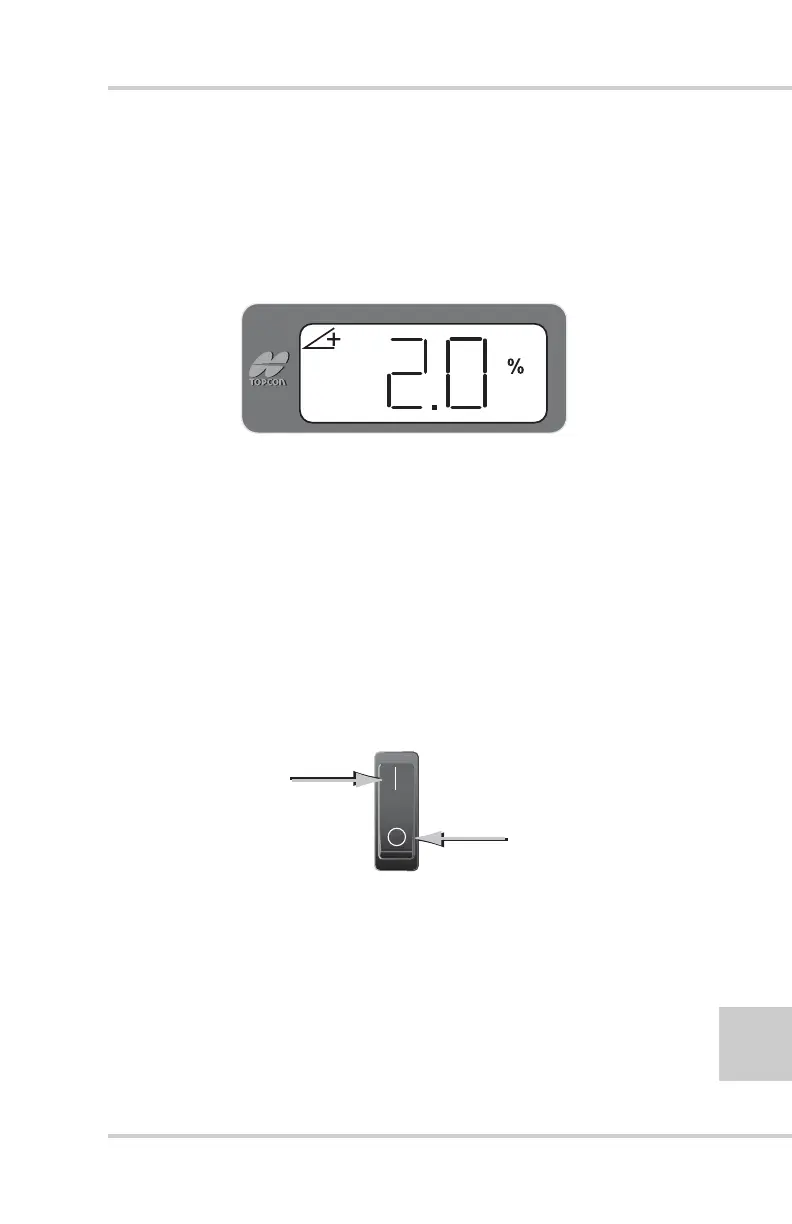
The LCD (Liquid Crystal Display) allows the operator to view
text and graphic symbols that represent elevation or slope
settings that System Five
TM
currently maintains for the paver
(Figure 4-2).
Figure 4-2. LCD Display
Light Sensor for LED Display
The light sensor monitors ambient light to adjust the brightness
of the LED display for better visibility.
The light sensor is located above the power switch.
Power Switch
The power switch (Figure 4-3) for the System Five Control Box
turns it on and off.
Figure 4-3. Power Switch
O
N
OFF

Table of Contents

Questions and Answers:

Question and Answer IconNeed help?

Do you have a question about the Topcon Paver System 5 and is the answer not in the manual?

Topcon Paver System 5 Specifications

General IconGeneral
BrandTopcon
ModelPaver System 5
CategoryControl Systems
LanguageEnglish

Related product manuals