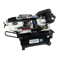
3. Slide the outfeed guide over the two screws. Adjust the
return tray so that it's in the pan, as shown in the
following image.
Figure 4-13: Outfeed guide correctly aligned.
4. Tighten the two Phillips head screws with a Phillips head
screwdriver.
4.4.5 Remove the Shipping Bolts on the Rear Cage
The rear cage is secured to the frame for shipment.
Remove the two bolts with a 5 mm hex wrench.
Figure 4-14: Removing the shipping bolts from the
rear cage and the frame.
4.4.6 Verify Motor Belt Tension
To properly validate the installation of your machine, you must
verify that the motor belt is properly tensioned.
To verify the motor belt tension:
1. Verify that the air supply and the machine's main power
cable aren't yet connected to the machine.
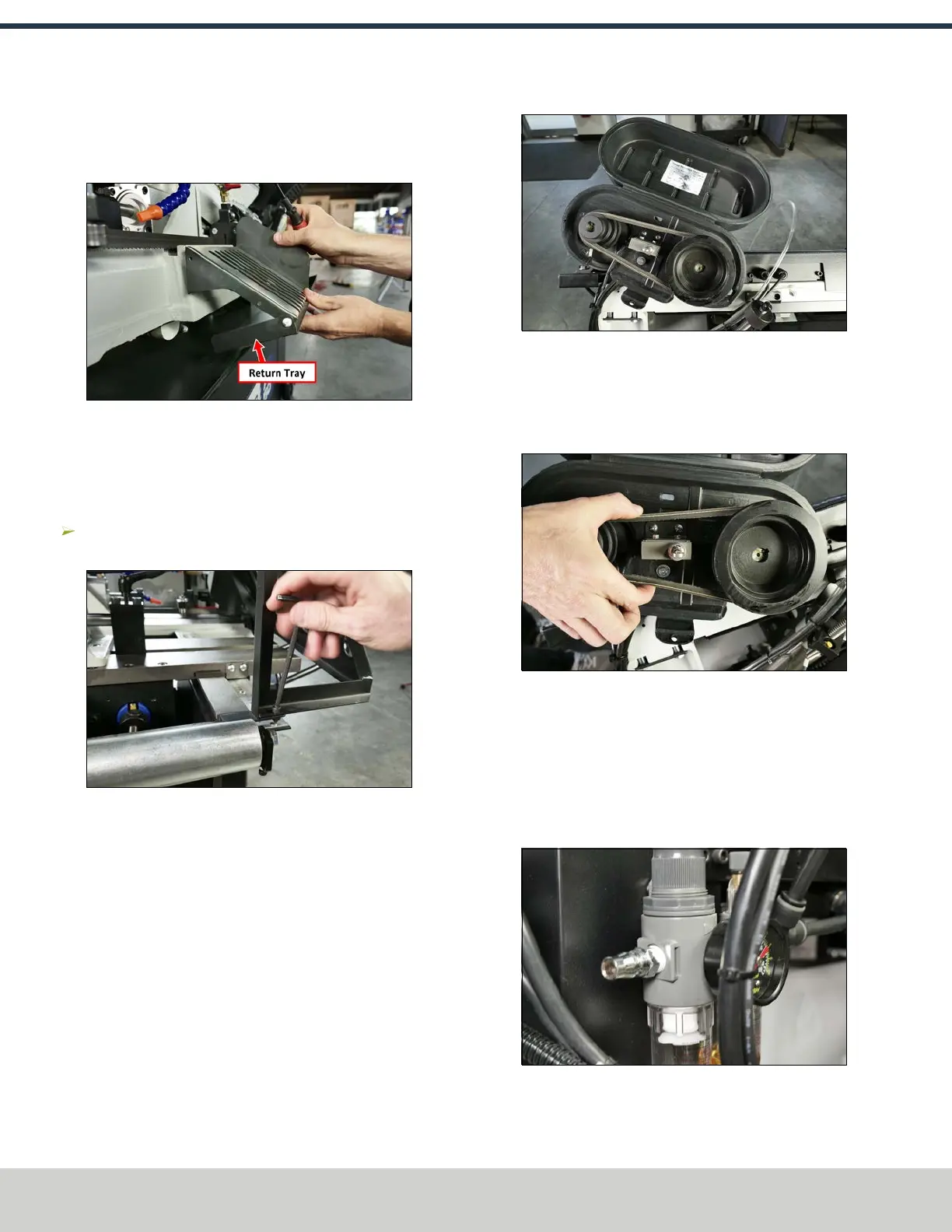
2. Open the pulley cover.
Figure 4-15: Pulley cover opened.
3. Firmly push the belt between the pulleys. If it's properly
tensioned, the belt should move approximately 1/2 in. If
it's not properly tensioned, complete the steps in
"Change the Speed" (page34).
Figure 4-16: Testing the tension of the motor belt.
4. Close the pulley cover.
4.4.7 Make Air Connections
1. Remove the fitting from the input port on the FRLFilter-
Regulator-Lubricator (on the back of the machine) with
an adjustable wrench.
Figure 4-17: Original air fitting installed on the FRL.
©Tormach® 2024
Specifications subject to change without notice.
Page 24 UM10825: AF50+ Autofeed Bandsaw Operator's Manual (Version 0324A)
For the most recent version, see tormach.com/support
4: INSTALLATION