RingtoPinionGearEngagement(FrontAxle)
Finalpositionofthefrontaxlepinionisveriedbyusingthegearcontactpattern
methodasdescribedinthefollowingprocedure.
g226484
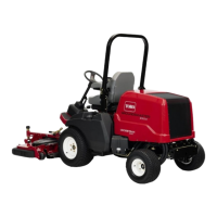
Figure248
1.T opland3.T oe5.Lengthwisebearingarc
2.Prole
4.Heel6.Root
Geartoothdenitions(Figure248):
•Toe-theportionofthetoothsurfaceattheendtowardthecenter.
•Heel-theportionofthegeartoothattheouterend.
•TopLand-topsurfaceoftooth.
1.Painttheteethoftheringgear,bothdriveandcoastside,withagearmarking
compound,suchasDyKem®steelblue.
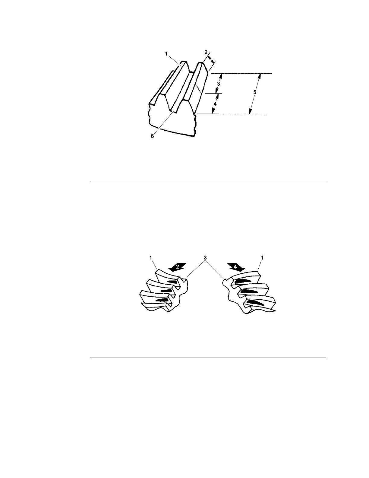
g226485
Figure249
1.Heel3.T oe
2.Driveside
4.Coastside
2.Whileapplyingalightloadtotheringgear,rotatethepiniongearuntilthe
ringgearhasmade1completerevolution.Thedrivesidepatternshouldbe
locatedatthetoeportionofthetooth.Thecoastpatternshouldalsobeatthe
toeportionofthetooth(Figure249).
Studythepatternsinthefollowingillustrationsandcorrectengagementas
necessary.
Note:Whenmakingchanges,notethat2variablesareinvolved.Example:
Ifyouhavethebacklashsetcorrectlytospecicationsandyouchange
thepinionpositionshim,youmayhavetoadjustbacklashtothecorrect
specicationbeforecheckingthepattern.
DriveAxles:ServiceandRepairs
Page8–40
Groundsmaster
®
3280-D/3320
05138SLRevB

 Loading...