4 Replacement Procedures 4.20 System board
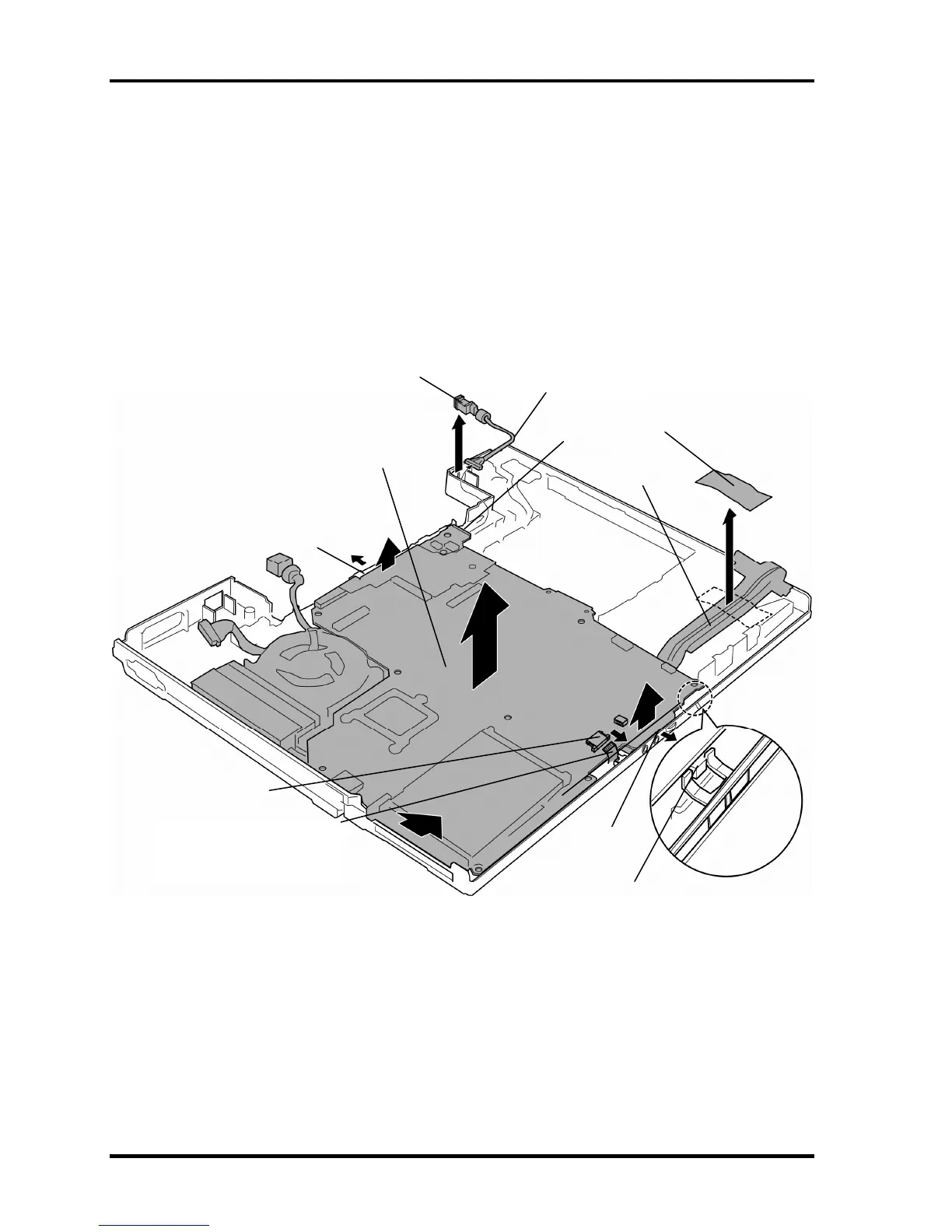
2. Disconnect the DC-IN jack cable from the connector CN8800 on the system board.
3. Peel off the glass tape and take out the HDD cable from the slot. (Be careful,
because the HDD cable is still connected to the connector on the back of the system
board.)
4. Disconnect the SmartCard unit cable from the connector CN2170 on the system
board.
5. Remove the system board while releasing two latches.
DC-IN jack
System board
Glass tape
HDD cable
Latch
Latch
CN8800
Wireless communication switch
DC-IN jack cable
CN2170
SmartCard unit cable
artCard model only) (Sm
Figure 4-33 Removing the system board
4-54 [CONFIDENTIAL] TECRA A9/TECRA S5/TECRA P5/Satellite Pro S200 Maintenance Manual (960-633)

 Loading...