E6580516
(3) Status alarms
Alarm
characters
and
the
frequency setting
may
be
alternately displayed
on
the
LED
in
standard
monitor
mode.
The
following
four
types of characters
may
be
displayed.
C ···When current exceeding
the
overcurrent
stall
level flows.
P ···When voltage exceeding the overvoltage
stall
level
is generated.
L ···When
50%
or
more
of
the
overload trip
value
is
reached.
H ···When
the
temperature
reaches
the overheat protection
alarm
setting
level.
Several alarms
may
also
be
displayed simultaneously.("
LC
11 11
PC "
11
L PC
11
)
The
alarms will automatically
go
out
when
the
alarm
condition
is
removed.
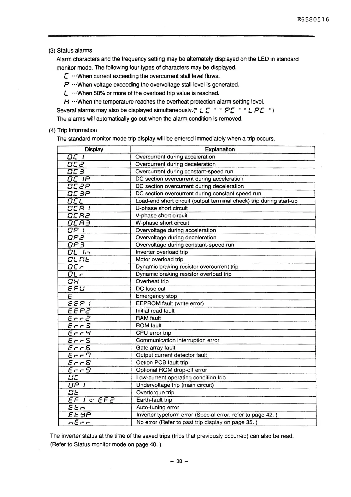
(4)
Trip information
The
standard monitor
mode
trip display
will
be
entered immediately
when
a trip occurs.
Display Explanation
,-,
,-
'
Overcurrent during acceleration
wr_
I
0[2
Overcurrent during deceleration
0[3
Overcurrent during constant-speed run
,-,
,-
IP
DC section overcurrent during acceleration
wr_
OC2P
DC section overcurrent during deceleration
OC3P
DC section overcurrent during constant speed run
,-,
,-
I
Load-end short circuit (output terminal check) trip during start-up
,_,
,_ ,_
oc.c:
I
U-phase short circuit
I
OCA2
V-phase short circuit
oc.c:3
W-phase short circuit
OP
I
Overvoltage during acceleration
I
0F'2
Overvoltage during deceleration
OP3
Overvoltage during constant-speed run
,-,
I
: ,-,
Inverter overload trip
,_,
,_
,-, ' ,-,
,_
wr_
'·~
Motor overload trip
oc.-
Dynamic braking resistor overcurrent trip
OL.-
Dynamic braking resistor overload trip
0:-1
Overheat trip
EFU
DC fuse cut
E
Emergency stop
EEP
,
EEPROM fault (write error)
I
EEP2
Initial read fault
E.-,-2
RAM fault
E.-,-
3
ROM fault
E ,- .- '-I
CPU error trip
E,-,-5
Communication interruption error
E.-,-5
Gate array fault
E.-,-'1
Output current detector fault
E.-,-8
Option PCB fault trip
E.-,-9
Optional ROM drop-off error
I
I,..
Low-current operating condition trip
wr_
UP
'
Undervoltage trip (main circuit)
I
Of=
Overtorque trip
EF
,
or
EF2
Earth-fault trip
I
El=,-,
Auto-tuning error
EI::
'=IP
Inverter typeform error (Special error, refer to page 42. )
,-,E ,- ,-
No error (Refer to past trip display on page 35. )
The
inverter
status
at
the
time of
the
saved
trips (trips
that
previously
occurred)
can
also
be
read.
(Refer
to
Status monitor
mode
on
page
40.
)
-
38
-

 Loading...


