CDHH-SVX003C-EN
29
Note: When installed, the tip of the ifm efector® sensor
probe must be at least 1 in. (2.54 cm) away from
any pipe wall. Do NOT insert more than 3.5 in.
(8.9 cm) of the probe length into the pipe.
3. Install the Micro DC Cable by inserting it through the
wire openings on the back side of the control panel
(see item labeled “3” in the preceding figure). Install the
supplied Micro DC Cable (29.5 ft [9 m] in length) to the
Flow Probe and hand-tighten the connector nut.
4. Plug the other end of the Micro DC Cable into the Flow
Control Monitor with the Combicon connector (see item
labeled “4” in the preceding figure). Refer to the
following figure for cable wiring.
NOTICE
Do Not Apply Electrical Power to a
Unit in a Vacuum!
Failure to follow instructions below could result in
motor and compressor damage.
Do not apply electrical power to a motor in a
vacuum.
For units with inside-the-delta solid state starters,
disconnect power to unit during evacuation or
when the unit is in a deep vacuum. In addition, on
units with inside-the-delta solid state starters, all
power to the unit must be disconnected prior to
evacuating the unit as line power is directly
applied to the motor terminals 4, 5, and 6.
Note: Graphic labels (shown above) are used for CE
application only.
Important:
• Before servicing, disconnect all power
sources and allow at least 30 minutes
for capacitors to discharge.
• All electrical enclosures—unit or
remote—are IP2X.
5. Apply power to the chiller control panel to verify the
Flow Control Monitor has power and the Low Volt
Broken Wire Relay light is NOT lit.
6. Remove all air from the piping circuit prior to adjusting
the low water flow setpoint.
7. Reduce the water flow to the minimum allowable flow
and adjust the Flow setting on the Flow Control Monitor
(see item labeled “7” in the following figure). Adjusting
the “Flow” potentiometer clockwise (+) reduces the flow
setting cutout and adjusting counterclockwise (-)
increases the flow setting cutout.
Note: The “Temp” potentiometer on the ifm efector®
control module has no effect in Trane application.
It is NOT necessary to make adjustments to the
“Temp” potentiometer.
8. After the cutout setting is adjusted, the cutout setpoint
will be indicated with a yellow light on the Flow Control
Monitor LED bar graph display. When the water flows
are higher than the cutout, a green light will indicate
proper flow status. If the flows fall below the cutout
setpoint, a red light will indicate low/no flow status.
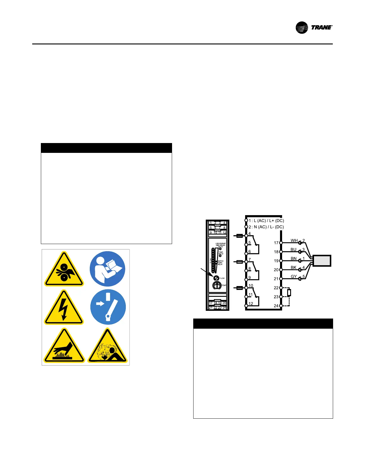
Figure 14. ifm efector® flow sensing device terminal
connection
NOTICE
Proof of Flow Switch!
Failure to provide flow switches or jumping-out of
switches could result in severe equipment damage.
Evaporator and condenser water circuits require
proof of flow switches.
• Failure to include the proof of flow devices and/or
jumping out these devices could cause the unit to
stop on a secondary level of protection.
• Frequent cycling on these higher level diagnostic
devices could cause excessive thermal and pressure
cycling of unit components (O-rings, gaskets,
sensors, motors, controls, etc.) and/or freeze damage,
resulting in premature failure of the chiller.
Evaporator and condenser proof of flow switches are
required. These switches are used with control logic to
Installation: Water Piping