CDHH-SVX003C-EN
33
Victaulic Gasket Installation
1. Inspect supplied gasket to be certain it is suited for
intended service (code identifies gasket grade). Apply a
thin coat of silicone lubricant to gasket tips and outside
of gasket.
2. Install gasket, placing gasket over pipe end and making
sure gasket lip does not overhang pipe end. Refer to
the following figure for gasket configuration.
3. Align and bring two pipe ends together and slide gasket
into position centered between the grooves on each
pipe. No portion of the gasket should extend into the
groove on either pipe.
4. Open fully and place hinged Victaulic® flange around
the grooved pipe end with the circular key section
locating into the groove.
5. Insert a standard hex head screw through the mating
holes of the Victaulic® flange to secure the flange firmly
in the groove.
6. Tighten fasteners alternately and equally until housing
screw pads are firmly together (metal-to-metal); refer to
“Screw-Tightening Sequence for Water Piping
Connections,” p. 33. Do NOT excessively tighten
fasteners.
Note: Uneven tightening may cause the gasket to pinch.
Figure 21. Typical Victaulic
®
flange gasket
configuration
Table 12. Installation data for 150 psig (1034.2 kPaG) flange adapters (Style 741)
Nominal Pipe Size
Assembly Screw
Size
(a)
Number of Assembly
Screws Required
Screw Pattern Diameter
Weight
in. mm in. in. mm lb
kg
8 200 3/4 x 3-1/2 8 11.75 298 16.6 7.5
10 250 7/8 x 4 12 14.25 362 24.2 11
12 300 7/8 x 4 12 17 432 46.8 21.2
14 350 1 x 4-1/2 12 18.75 476 62 28.1
16 400 1 x 4-1/2 16 21.25 540 79 35.8
18 450 1-1/8 x 4-3/4 16 22.75 578 82.3 37.3
20 500 1-1/8 x 5-1/4 20 25 635 103.3 46.9
24 600 1-1/4 x 5-3/4 20 29.5 749 142 64.4
(a)
Screw size for conventional flange-to-flange connection. Longer screws are required when flange washer must be used.
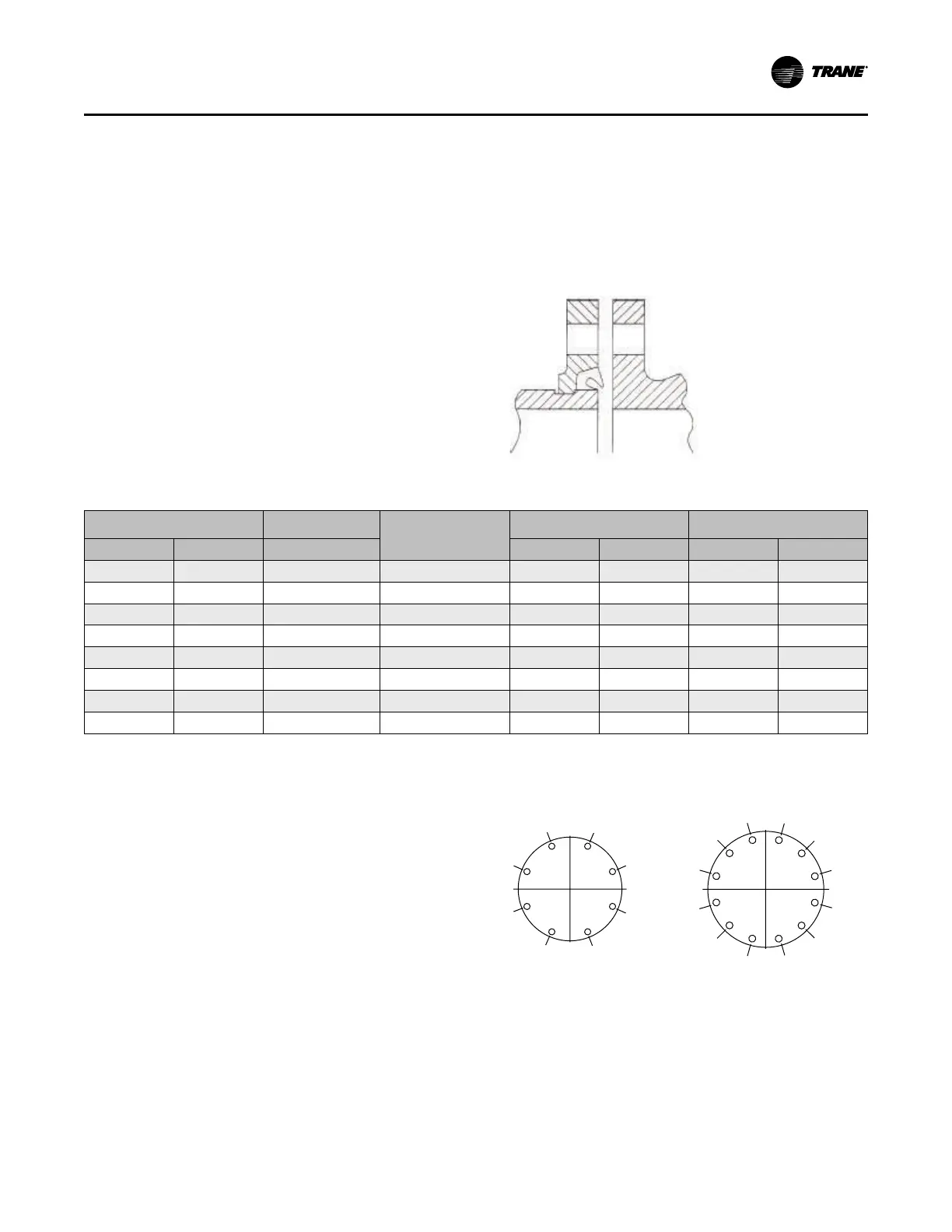
Screw-Tightening Sequence for
Water Piping Connections
This section describes a screw-tightening sequence for
flanges with flat gaskets or O-rings. Remember that
improperly tightened flanges may leak.
Note: Before tightening any of the screws, align the flanges.
Flanges with 8 or 12 Screws
Tighten all screws to a snug tightness, following the
numerical sequence for the appropriate pattern as shown
in the following figure. Repeat this sequence to apply the
final torque to each screw.
Figure 22. Flange screw tightening sequence (8 or 12
screws)
1
3
4 5
7
8
2 6
8 screws
1
3
4
10 11
9
5
7
8
12
26
12 screws
Flanges with 16 or 20 Screws
Tighten only the first half of the total number of screws to a
snug tightness, following the numerical sequence for the
appropriate pattern as shown in the following figure. Next,
sequentially tighten the remaining half of the screws in
numerical order.
Installation: Water Piping