54
CDHH-SVX003C-EN
Table 16. Wire sizing reference (continued)
AWG/MCM
mm
2
Equivalent
20 0.5
18 0.75
17 1.0
16 1.5
14 2.5
12 4
10 6
8 10
6 16
4 25
2 or 1 35
1/0 50
2/0 70
2/0 or 3/0 95
4/0 or 250 120
300 150
350 or 400 185
450 or 500 240
Note: AWG = American Wire Gauge.
Important: Customers are responsible for all field wiring in
compliance with international, national, and/or
local codes.
WARNING
Hazardous Voltage w/Capacitors!
Failure to disconnect power and discharge capacitors
before servicing could result in death or serious
injury.
Disconnect all electric power, including remote
disconnects and discharge all motor start/run
capacitors before servicing. Follow proper lockout/
tagout procedures to ensure the power cannot be
inadvertently energized. For variable frequency drives
or other energy storing components provided by
Trane or others, refer to the appropriate
manufacturer’s literature for allowable waiting periods
for discharge of capacitors. Verify with a CAT III or IV
voltmeter rated per NFPA 70E that all capacitors have
discharged.
WARNING
Personal Protective Equipment (PPE)
Required!
Failure to wear PPE and follow proper handling
guidelines could result in death or serious injury.
Always wear appropriate personal protective
equipment in accordance with applicable regulations
and/or standards to guard against potential electrical
shock and flash hazards.
WARNING
Live Electrical Components!
Failure to follow all electrical safety precautions when
exposed to live electrical components could result in
death or serious injury.
When it is necessary to work with live electrical
components, have a qualified licensed electrician or
other individual who has been properly trained in
handling live electrical components perform these
tasks.
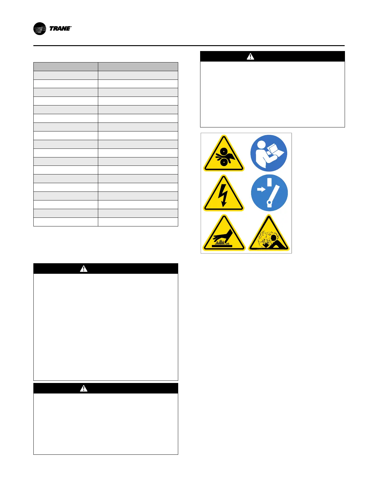
Note: Graphic labels (shown above) are used for CE
application only.
Important:
• Before servicing, disconnect all power
sources and allow at least 30 minutes for
capacitors to discharge.
• All electrical enclosures—unit or remote—
are IP2X.
Trane-supplied Remote Starter
Wiring
This information is applicable to Starter 1 for Compressor 1
as well as Starter 2 for Compressor 2. (For wire estimation
purposes, double check the following table as there are two
starters to be wired.).
Important: The information in the table below is applicable
to Standard Starters or Drive Options. Consult
As-Builts, Submittal and/or consult Tech
Support for Sales orders with design special
drives and starters.
Electrical Requirements