70
CDHH-SVX003C-EN
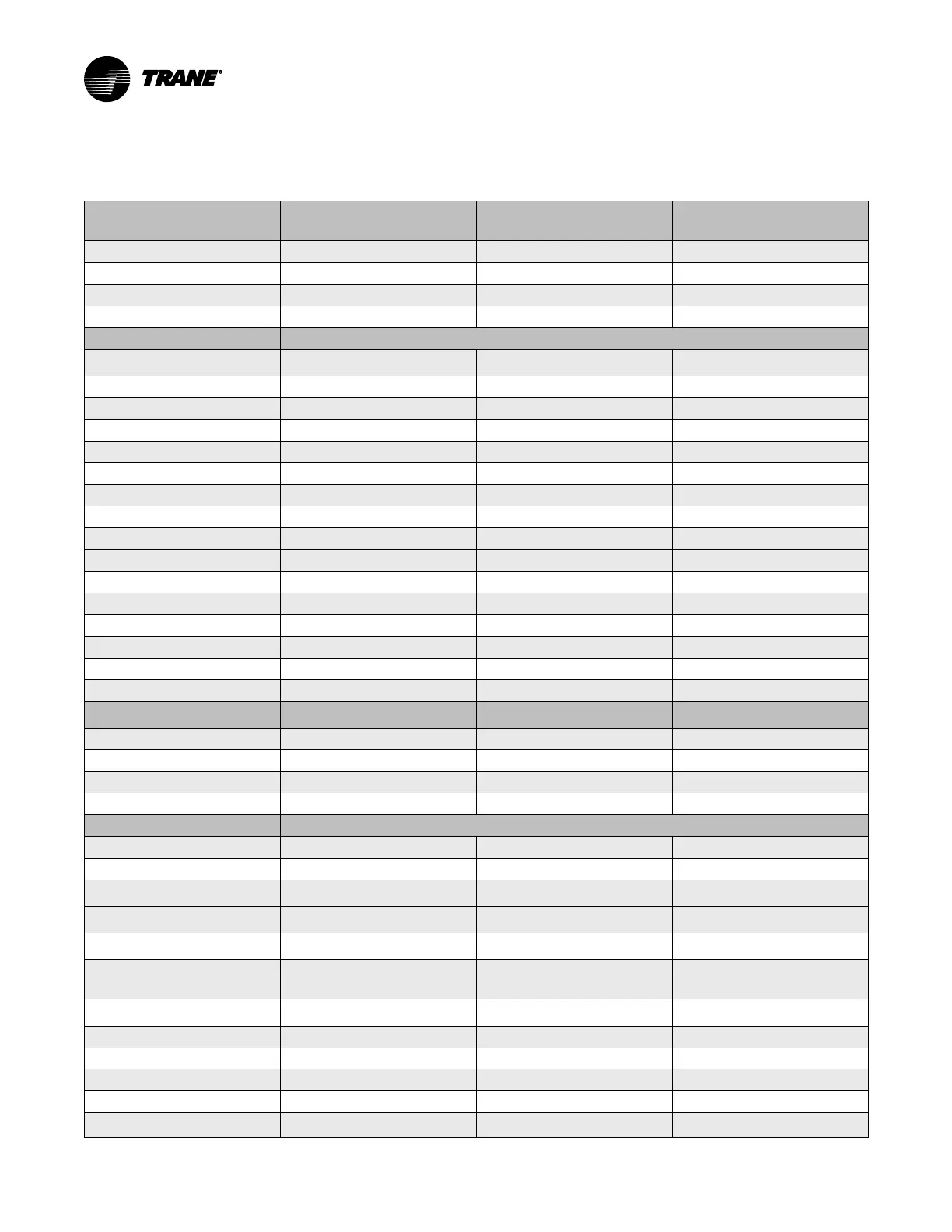
System Control Circuit Wiring (Field Wiring)
Table 23. Unit control panel wiring 120 Vac
Standard Control Circuits: Unit
Control Panel Control Wiring
(120 Vac)
Unit Control Terminations
Input or Output Type
Contacts
Chilled Water Flow Proving Input
(a)
1X1-5 to 1K16-J3-2 Left Panel
Binary Input Normally Open, Closure with Flow
Condenser Water Flow Proving Input
(b)
1X1-6 to 1K16-J2-2 Left Panel
Binary Input Normally Open, Closure with Flow
Chilled Water Pump Relay Output
1K15-J2-4 to 6 Left Panel
Binary Output Normally Open
Condenser Water Pump Relay Output
1K15-J2-1 to 3 Left Panel
Binary Output Normally Open
Optional Control Circuits (120 Vac) Note: Defaults are factory programmed; alternates can be selected at start-up using the service tool.
Alarm Relay MAR (Non-Latching)
Output
1K19-J2-1 to 3 Left Panel
Binary Output Normally Open
Limit Warning Relay Output
1K19-J2-4 to 6 Left Panel
Binary Output Normally Open
Alarm Relay MMR (Latching) Output
1K19-J2-7 to 9 Left Panel
Binary Output Normally Open
Compressor Running Relay Output
1K19-J2-10 to 12 Left Panel
Binary Output Normally Open
Maximum Capacity Relay Output
1K20-J2-1 to 3 Left Panel
Binary Output Normally Open
Head Relief Request Relay Output
1K20-J2-4 to 6 Left Panel
Binary Output Normally Open
Circuit 2 Purge Alarm Relay Output
1K20-J2-7 to 9 Left Panel
Binary Output Normally Open
Circuit 1 Purge Alarm Relay Output
1K20-J2-10 to 12 Left Panel
Ice Making Relay Output
1K15-J2-10 to 12 Left Panel
Binary Output Normally Open
Alternates
Circuit 1 Running
Circuit 2 Running
Chiller Alarm
Circuit 1 Alarm
Circuit 2 Alarm
Purge Alarm
Standard Low Voltage Circuits (Less
than 30 Vac)
(c)
Unit Control Panel Terminations
Input or Output Type
Contacts
External Auto Stop Input
1K2-J2-1 to 2 Left Panel
Binary Input Closure Required for Normal Operation
Emergency Stop Input
1K2-J2-3 to 4 Left Panel
Binary Input Closure Required for Normal Operation
Circuit 1 External Lockout 12K11-J2-1 to 2 Left Panel
Binary Input Closure Required for Normal Operation
Circuit 2 External Lockout 1K211-J2-3 to 4 Left Panel
Binary Input Closure Required for Normal Operation
Optional Low Voltage Circuits
External Base Loading Enable Input
1K8-J2-1 to 2 Left Panel
Binary Input Normally Open
External Hot Water Control Enable Input
1K8-J2-3 to 4 Left Panel
Binary Input Normally Open
External Ice Building Control Enable
Input
1K9-J2-1 to 2 Left Panel
Binary Input Normally Open
% RLA Compressor Output (Circuit 1
Left Panel 1K5)
1K5-J2-1 to 3 Left Panel
Analog Output
2–10 Vdc
External Condenser Pressure Output
(Circuit 1 Left Panel 1K5)
1K5-J2-4 to 6 Left Panel
Analog Output
2–10 Vdc
Evaporator/Condenser Differential
Pressure Output (Circuit 1 Left Panel
1K5)
1K5-J2-4 to 6 Left Panel
Analog Output
2–10 Vdc
Condenser Head Pressure Control
(Circuit 1 Left Panel 1K5)
1K5-J2-4 to 6 Left Panel
Analog Output
2–10 Vdc
External Demand Limit Setpoint Input
1K6-J2-2 to 3 Left Panel
Analog Input
2–10 Vdc, or 4–20 mA
External Chilled Water Setpoint Input
1K6-J2-5 to 6 Left Panel
Analog Input
2–10 Vdc, or 4–20 mA
External Base Loading Setpoint Input
1K7-J2-2 to 3 Left Panel
Analog Input
2–10 Vdc, or 4–20 mA
Generic Refrigerant Monitor Input
1K7-J2-5 to 6 Left Panel
Analog Input
2–10 Vdc, or 4–20 mA
Outdoor Air Temperature Sensor
Inter-processor Communication (IPC)
Bus Connection and Sensor
Communication and Sensor