30
CDHH-SVX003C-EN
confirm flow prior to starting a unit and to stop a running
unit if flow is lost. For troubleshooting, a viewable
diagnostic is generated if a proof of flow switch does not
close when flow is required.
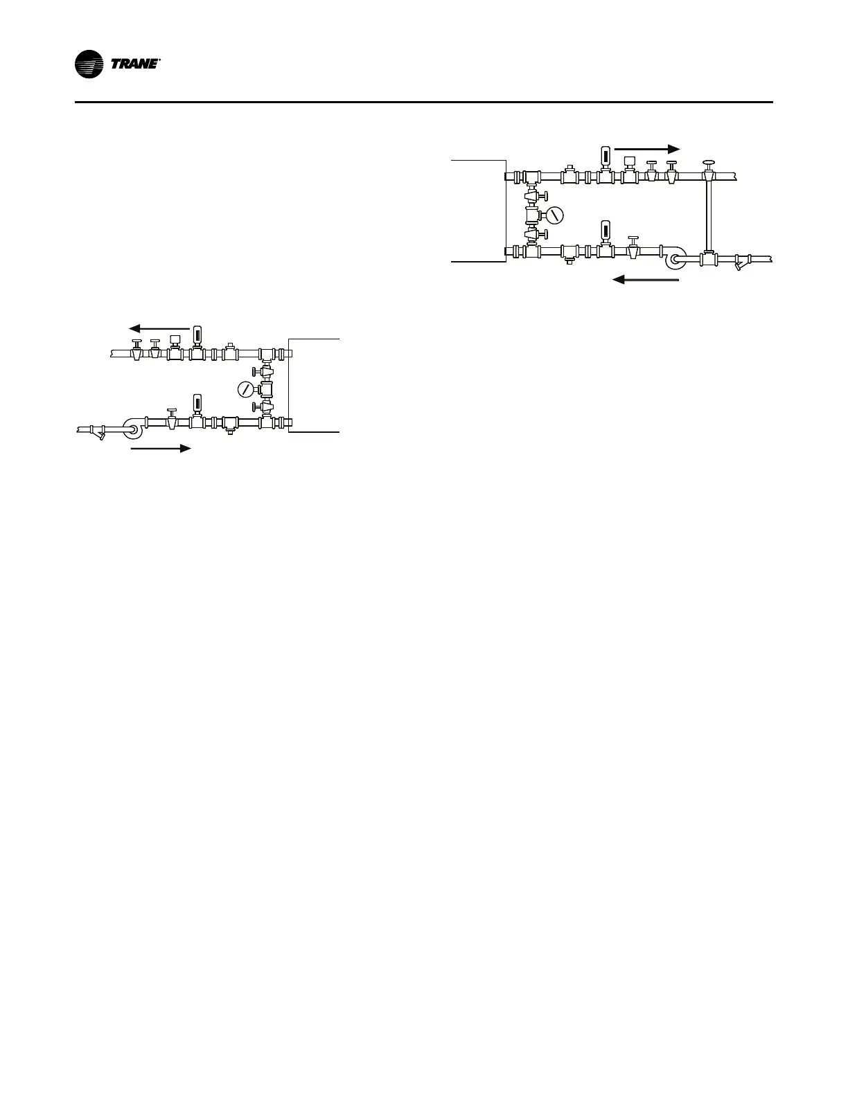
Evaporator and Condenser
Water Piping
The following two figures illustrate the recommended
(typical) water piping arrangements for the evaporator and
condenser.
Figure 15. Typical evaporator water piping circuit
4
45
53
3
7
2
2 1
9
6
2
2
8
Outlet
Inlet
1. Balancing valve.
2. Gate (Isolation) valve or ball valve.
3. Thermometer (if field supplied).
4. Waterbox nozzle connection.
5. Drain, vent, and anode.
6. Strainer.
7. Chilled water flow switch (4B4). Flow switch 4B4 may
be installed in either the entering or leaving leg of the
chilled water circuit.
8. Pump.
9. Pressure gauge. It is recommended to pipe the gauge
between entering and leaving pipes. A shutoff valve on
each side of the gauge allows the operator to read
either entering or leaving water pressure.
Figure 16. Typical condenser water piping circuits
1 2
3
4 5
6
7 8
92
3
4 5
2
2
10
Outlet
Inlet
1. Balancing valve.
2. Gate (isolation) valve or ball valve.
3. Thermometer (if field supplied).
4. Waterbox nozzle connection.
5. Drain, vent, and anode.
6. Strainer.
7. Condenser water flow switch (4B5). Flow switch 4B5
may be installed in either the entering or leaving leg of
the water circuit.
8. Three-way valve (optional).
9. Condenser water pump.
10. Pressure gauge. It is recommended to pipe a single
gauge between entering and leaving pipes.
Notes:
• Some type of field-supplied temperature control
device may be required to regulate the
temperature of the heat-recovery condenser
water circuit. For application recommendations,
refer to Heat Recovery Seminar (Part 2):
Systems/Equipment (AM-FND-8).
• Install a bypass valve system to avoid
circulating water through the auxiliary shell
when the unit is shutdown.
• On multiple-pass condensers, entering
condenser water must enter at the lowest
nozzle.
Piping must be arranged and supported to avoid stress on
the equipment. It is strongly recommended that the piping
contractor does not run pipe closer than 3 ft (0.9 m)
minimum to the equipment. This will allow for proper fit
upon arrival of the unit at the job site. Any adjustment that
is necessary can be made to the piping at that time.
Expenses that result from a failure to follow this
recommendation will NOT be paid by Trane.
Waterboxes with multiple pass arrangements utilize a
baffle to separate the passes. These baffles are designed
for a maximum pressure of 20 psid (137.9 kPaD). If larger
pressure drops are expected in the application, contact
your local Trane representative to discuss special waterbox
options.
Important: Water flows must be piped in accordance with
nameplate designation.
Installation: Water Piping