CDHH-SVX003C-EN
71
Table 23. Unit control panel wiring 120 Vac (continued)
BACnet
®
or MODBUS
®
1K1–P1 Left Panel
Communication to BACnet
®
or
MODBUS
®
(As Ordered; See Sales Order)
LON Interface 1K25 Left Panel Communication to LonTalk
®
(As Ordered; See Sales Order)
Right Hand Control Panel
Optional Low Voltage Circuits
% RLA Compressor 2 Output (Circuit 2
Right Panel 1K5)
1K5-J2-1 to 3 Right Panel Analog Output
2–10 Vdc
External Condenser Pressure Output
(Circuit 2 Right Panel 1K5)
1K5-J2-4 to 6 Right Panel Analog Output
2–10 Vdc
Note: All wiring to be in accordance with National Electrical Code (NEC) and any local codes.
(a)
If the Chilled Water Flow Proving Input is a factory-installed ifm efector flow-sensing device, the secondary field device (recommended with 38°F [3.3°C] and lower leaving
chilled water temperatures) for proof of flow connects from 1X1-5 to 1K26-4 (binary input; normally open, closure with flow). Remove factory jumper when used.
(b)
If the Condenser Water Flow Proving Input is a factory-installed ifm efector flow-sensing device, the secondary (optional) field device for proof of flow connects from 1X1-6 to
1K27-4 (binary input; normally open, closure with flow). Remove factory jumper when used.
(c)
Standard low-voltage circuits (less than 30 Vac) must be separated from 120 Vac or higher wiring.
Water Pump Interlock Circuits
and Flow Switch Input
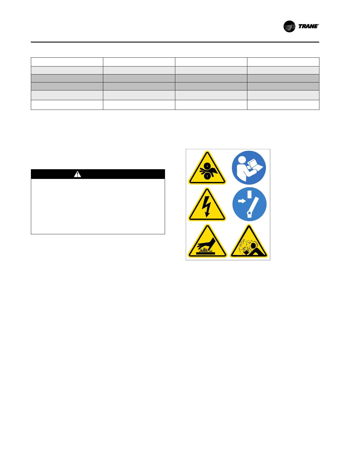
WARNING
Hazardous Voltage!
Failure to disconnect power before servicing could
result in death or serious injury.
Disconnect all electric power, including remote
disconnects before servicing. Follow proper lockout/
tagout procedures to ensure the power can not be
inadvertently energized. Verify that no power is
present with a voltmeter.
Note: Graphic labels (shown above) are used for CE
application only.
Important:
• Before servicing, disconnect all power
sources and allow at least 30 minutes for
capacitors to discharge.
• All electrical enclosures—unit or remote—
are IP2X.
Note: The circuits for the chilled water proof of flow and the
condenser water proof of flow do NOT require
external power. Refer to the wiring diagrams that
shipped with the chiller.
System Control Circuit Wiring (Field Wiring)