CDHH-SVX003C-EN
79
Simultaneous Compressor Start/Stop
Both compressors will start in close succession to minimize
the time it takes for the chiller to reach full load. Some
process applications need the chiller to start and generate
capacity as fast as possible. This method will start both
compressors, slightly staggered to prevent doubling of the
current inrush, but will generally control the chiller as if
there were only one compressor. If the chiller is in the Auto
mode and all interlocks have been satisfied, Compressor 1
will be started based on the leaving water temperature
rising above the “Differential to Start” setting. When
Compressor 1 is at speed, Compressor 2 will start. Both
compressors will run until water temperature falls below the
differential to stop, at that time both compressors will be
shutdown.
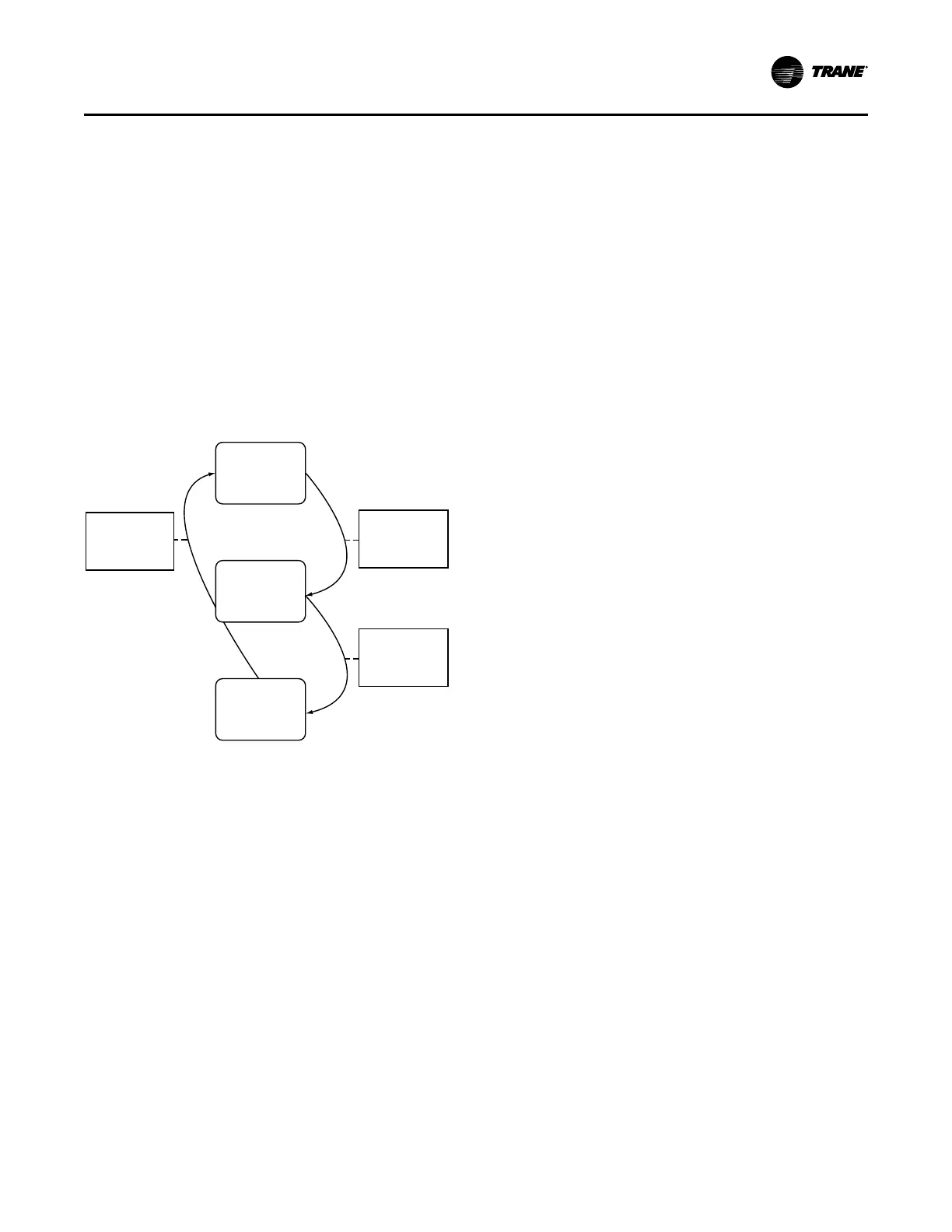
Figure 57. Duplex™ chiller sequence of operation:
combined start
Auto
Running
(Circuit 1)
Running
(Circuit
1 and 2)
Evap LWT Falls
Below
Differential to
Stop
Evap LWT Rises
Above
Differential to
Start
Confirm
Compressor A
Start, then
Immediately Start
Compressor B
Compressor Load Balancing
Duplex™ CenTraVac™ chillers with Tracer® AdaptiView™
Symbio™ 800 control will balance the compressor load by
giving each compressor the same load command. The load
command will be converted to inlet guide vane (IGV)
position that will be the same on each compressor.
Balancing compressor load results in the best overall
efficiency and with both circuits operating with nearly the
same refrigerant pressures. When both compressors are
running, the overall chiller load command will be split
evenly between the two compressors unless limit control
overrides balancing. When transitioning between one-
compressor operation and two-compressor operation, the
load commands will be actively balanced at a rate slow
enough to minimize capacity control disturbances.
Restart Inhibit. The purpose of restart inhibit feature is to
provide short cycling protection for the motor and starter.
The operation of the restart inhibit function is dependent
upon two setpoints.
Restart Inhibit Free Starts. The Restart Inhibit Free Starts
(default = 3, range from 1 to 5) is adjustable via the service
tool and will allow a number of rapid restarts equal to its
value. If the number of free starts is set to “1”, this will allow
only one start within the time period set by the Start to Start
Time Setting. The next start will be allowed only after the
start to start timer has expired. If the number of free starts
is programmed to “3”, the control will allow three starts in
rapid succession but thereafter, it would hold off on a
compressor start until the Start to Start timer expired.
Restart Inhibit Start to Start Time Setting. The Restart
Inhibit Start to Start Timer (default = 20 minutes, range
from 10 to 30 minutes) is adjustable via the service tool and
defines the shortest chiller cycle period possible after the
free starts have been used. If the number of free starts is
programmed to “1”, and the Start to Start Time Setting is
programmed to 20 minutes, then the compressor will be
allowed one start every 20 minutes. The start-to-start time
is the time from when the motor was commanded to
energize to when the next command to enter prestart is
given.
Clear Restart Inhibit. A Clear Restart Inhibit “button” is
provided within Manual Override in Settings on the Tracer®
AdaptiView™ display. This provides a way for an operator
to allow a compressor start when there is a currently active
Restart Inhibit that is prohibiting such a start. The “button”
press will have no other function than to remove the restart
inhibit if there is one active. It does not change the count of
any internal restart inhibit timers or accumulators. The
restart inhibit function, setpoints, and clear features exist
for each compressor and operate independently of other
compressors on that chiller. During the time the start is
inhibited due to the start-to-start timer, the Tracer®
AdaptiView™ shall display the mode “Restart Inhibit” and
the also display the time remaining in the restart inhibit. A
“Restart Inhibit Invoked” warning diagnostic will exist when
the attempted restart of a compressor is inhibited.
Oil and Refrigerant Pump
Compressor Lubrication System
A schematic diagram of the compressor lubrication system
is illustrated in the following figure. (This can be applied to
Circuit 1 or Circuit 2.) Oil is pumped from the oil tank (by a
pump and motor located within the tank) through an oil
pressure regulating valve designed to maintain a net oil
pressure of 20 to 24 psid (137.9 to 165.5 kPaD). It is then
filtered and sent to the braze plate heat exchanger oil
cooler located above the oil tank and on to the compressor
motor bearings. From the bearings, the oil drains back to
the oil tank.
Operating Principles