CDHH-SVX003C-EN
49
Installing the Tracer
®
AdaptiView™ Display
During shipment, the Tracer
®
AdaptiView™ display is
boxed, shrink-wrapped, and located behind the control
panel. The display must be installed at the site.
Important: For best results, Trane, or an agent of Trane,
must install the Tracer
®
AdaptiView™ display
and support arm.
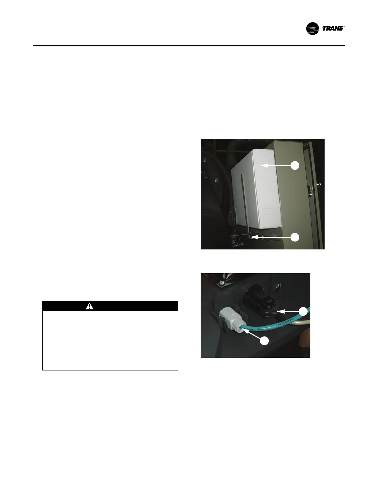
1. Unwrap the control panel and display arm. Locate the
box containing the Tracer
®
AdaptiView™ display
behind the control panel (labeled A in the following
figure).
2. After the box containing the display has been removed,
remove the shipping bracket from the back of the
control panel (labeled B in the following figure).
3. Remove the display from the box.
Note: Display screws are M4 (metric size 4), 6 to 8 mm
long, and are shipped with the display.
4. Symbio™ 800 will only work with AdaptiView™ part
number X13760359001 or greater. Check to ensure the
correct part number prior to installation.
Note: The previous AdaptiView™ display
(X13760326050) will only work with UC800
controllers.
5. Plug the power cable (labeled C in the following figure)
and the Ethernet cable (labeled D in the following
figure) into the bottom of the display.
Note: Both cables are already present and extend from
the end of the display arm.
6. Adjust the Tracer
®
AdaptiView™ display support arm
so the base plate that attaches to the display is
horizontal.
CAUTION
Tension in Display Support Arm!
Failure to follow instructions below could result in
unexpected movement of the spring-loaded
support arm which could result in minor to
moderate injury.
Ensure that the support arm is in the full upright
position when removing the Tracer AdaptiView
display from the support arm.
Note: Review “Adjusting the Tracer
®
AdaptiView™
Display Arm,” p. 50 before attaching the display
as some adjustments may be required prior to
attaching the display to the support arm base.
7. Position the Tracer
®
AdaptiView™ display with the
LCD screen facing up on top of the display support arm
base plate.
Note: Ensure the Trane logo is positioned so that it will
be at the top when the display is attached to the
display support arm.
Important: Use care when positioning the Tracer
®
AdaptiView™ display on top of the support
arm base plate and do NOT drop the
display.
8. Align the four holes in the display with the screw holes
in the display support arm base plate.
9. Attach the Tracer
®
AdaptiView™ display to the display
support arm base plate (labeled E in the following
figure) using the M4 (metric size 4) screws referenced
in step 3.
Figure 34. Tracer
®
AdaptiView™ shipping location
Figure 35. Power cable and Ethernet cable
connections
Installation: Controls