CDHH-SVX003C-EN
77
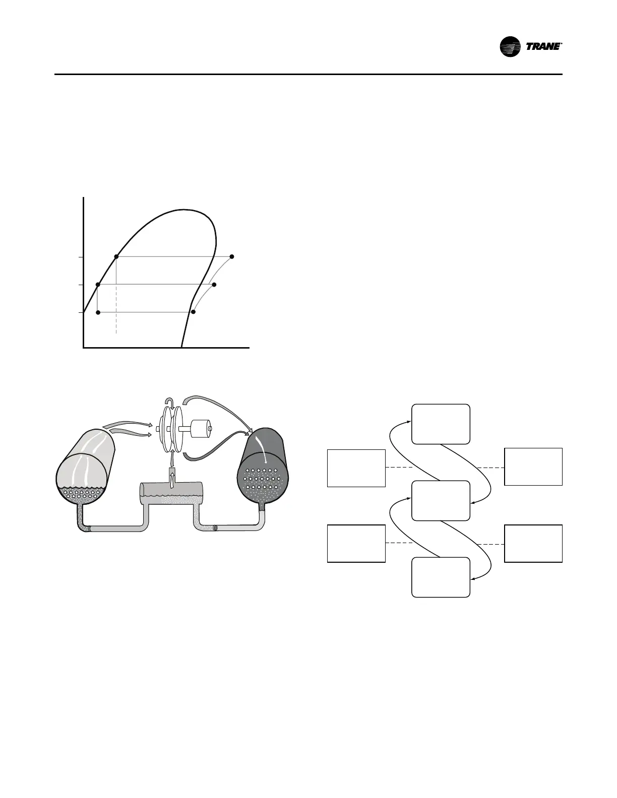
(refer to the following figure). Notice that some of the liquid
refrigerant flashes to a gas because of the pressure drop
created by the orifice plate, thus further cooling the liquid
refrigerant. This flash gas is then drawn directly from the
economizer into the second-stage impellers of the
compressor. All remaining liquid refrigerant flows out of the
economizer, passing through another orifice plate and into
the evaporator.
Figure 51. Pressure enthalpy curve
Condenser
Economizer
Evaporator
Compressor
Second Stage
Compressor
First Stage
6
5
4
3
1 2
Pressure
Enthalpy
P
3
P
1
P
2
Figure 52. Refrigerant flow, 2-stage
Duplex Compressor Sequencing
Four methods (two fixed-sequence methods, a balanced
start and hour’s method, and a no-staging method) are
provided for order of a compressor sequencing on
Duplex™ CenTraVac™ chillers. The desired method is
selectable at startup via the service tool. The application
can decide to either balance the wear burden among the
unit’s compressors, to start the most efficient compressor,
or to simultaneously start and stop both compressors to
minimize startup pull down time. Each method has specific
applications were it can be used advantageously. If one
compressor is locked out, in restart inhibit, or generally not
ready to start, the available compressor will be started.
Note: The following description assumes Compressor 1 is
the downstream compressor.
Fixed Sequence – Compressor 1 /
Compressor 2 (Default Mode)
If the chiller is in the Auto mode and all interlocks have
been satisfied, Compressor 1 will be started based on the
leaving water temperature rising above the “Differential to
Start” setting. Compressor 2 will stage on when the overall
chiller average capacity exceeds stage-on load point for
30 seconds. The stage-on load point is adjustable (via
service tool) up to 50 percent.
The default is 40 percent which means that a single
compressor would have to load to 80 percent (the average
would be 40 percent) before the second compressor starts.
Both compressors will run until chiller average capacity
drops below stage-off load point for 30 seconds. The stage-
off load point is also adjustable (via service tool) (default =
30 percent, range from 0 to 50 percent). Compressor 2 will
be shutdown and Compressor 1 will run until water
temperature drops below the differential to stop. Before
shutting down, Compressor 2 will be unloaded and
Compressor 1 will be loaded to maintain the same average
capacity command. When running chilled water
temperature at selected conditions, the downstream
compressor usually will be the most efficient compressor to
operate at part load because compressors on Duplex™
CenTraVac™ chillers are not sized exactly the same.
Figure 53. Duplex™ chiller sequence of operation:
lead 1 / lag 2
Auto
Evap LWT Falls
Below
Differential to
Stop
Evap
LWT Rises
Above
Differential to
Start
Running
(Circuit 1)
Running
(Circuit
1 and 2)
Chiller Capacity
Less than 30%
(No Time Delay)
Compressor A
Capacity Greater
than 80%
(No Time Delay)
Fixed Sequence – Compressor 2 /
Compressor 1
If the chiller is in the Auto mode and all interlocks have
been satisfied, Compressor 2 will be started based on the
leaving water temperature rising above the “Differential to
Start” setting. Compressor 1 will stage on when the overall
chiller average capacity exceeds stage on load point for
30 seconds. The stage-on load point is adjustable up to
50 percent.
Operating Principles