50
CDHH-SVX003C-EN
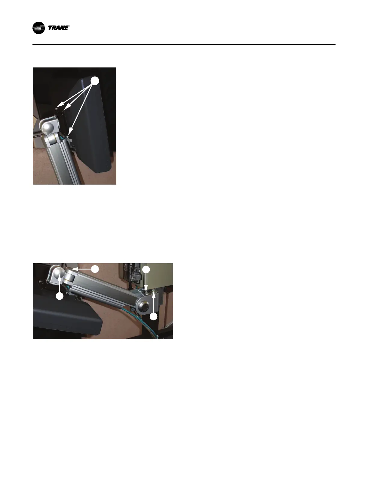
Figure 36. Display attachments to the support arm
base plate
Adjusting the Tracer
®
AdaptiView™ Display Arm
The Tracer
®
AdaptiView™ display arm may become too
loose or too tight and may need adjustment. There are
three joints on the display arm that allow the display to be
positioned at a variety of heights and angles (refer to items
labeled 1, 2, and 3 in the following figure).
Figure 37. Joint locations on the display arm
To adjust the tension on the display arm:
• At each joint in the display arm, there is either a hex
bolt (1 and 2) or hex screw (3). Turn the hex bolt or
screw in the proper direction to increase or decrease
tension.
Note: Each hex bolt or screw is labeled with loosen/
tighten or +/- indicators.
• Joint 3 has a 6 mm hex screw controlling the tension on
a gas spring, which allows the Tracer
®
AdaptiView™
display to tilt up and down.
• Joints 1 and 2 are covered by a plastic cap. Remove
the plastic cap to access the screw. Adjust using a
13 mm wrench as necessary.
• To adjust the swivel rotation tension of the Tracer
®
AdaptiView™ display, adjust the screw located in the
support arm base plate, as described in the final step in
the Installing the Tracer
®
AdaptiView™ Display
section.. This adjustment must be done prior to
attaching the display to the support arm base. Use a
14 mm wrench to adjust the tension.
• To adjust the left/right swivel of the entire display arm,
use a 13 mm wrench to adjust the screw labeled 4 in
the preceding figure.
Installation: Controls