28
CDHH-SVX003C-EN
Strainers
NOTICE
Water Borne Debris!
To prevent components damage, pipe strainers must
be installed in the water supplies to protect
components from water borne debris. Trane is not
responsible for equipment-only-damage caused by
water borne debris.
Install a strainer in the entering side of each piping circuit to
avoid possible tube plugging in the chiller with debris.
Required Flow-Sensing Devices
The ifm efector® flow detection controller and sensor (refer
to “Water Flow Detection Controller and Sensor – ifm
efector,” p. 28) is used to verify evaporator and condenser
water flows.
If a customer-supplied flow sensing device is used to
ensure adequate chiller flow protection, refer to the wiring
diagrams that shipped with the unit for specific electrical
connections.
Be sure to follow the manufacturer’s recommendations for
device selection and installation.
Water Flow Detection Controller and
Sensor – ifm efector
Important: Before installing the ifm efector® flow detection
controller and sensor, use a marker to draw a
line on the probe at 3.5 in. (8.9 cm) from the
end of the probe. Do NOT insert more than 3.5
in. (8.9 cm) of the probe length into the pipe.
Refer to the following figure.
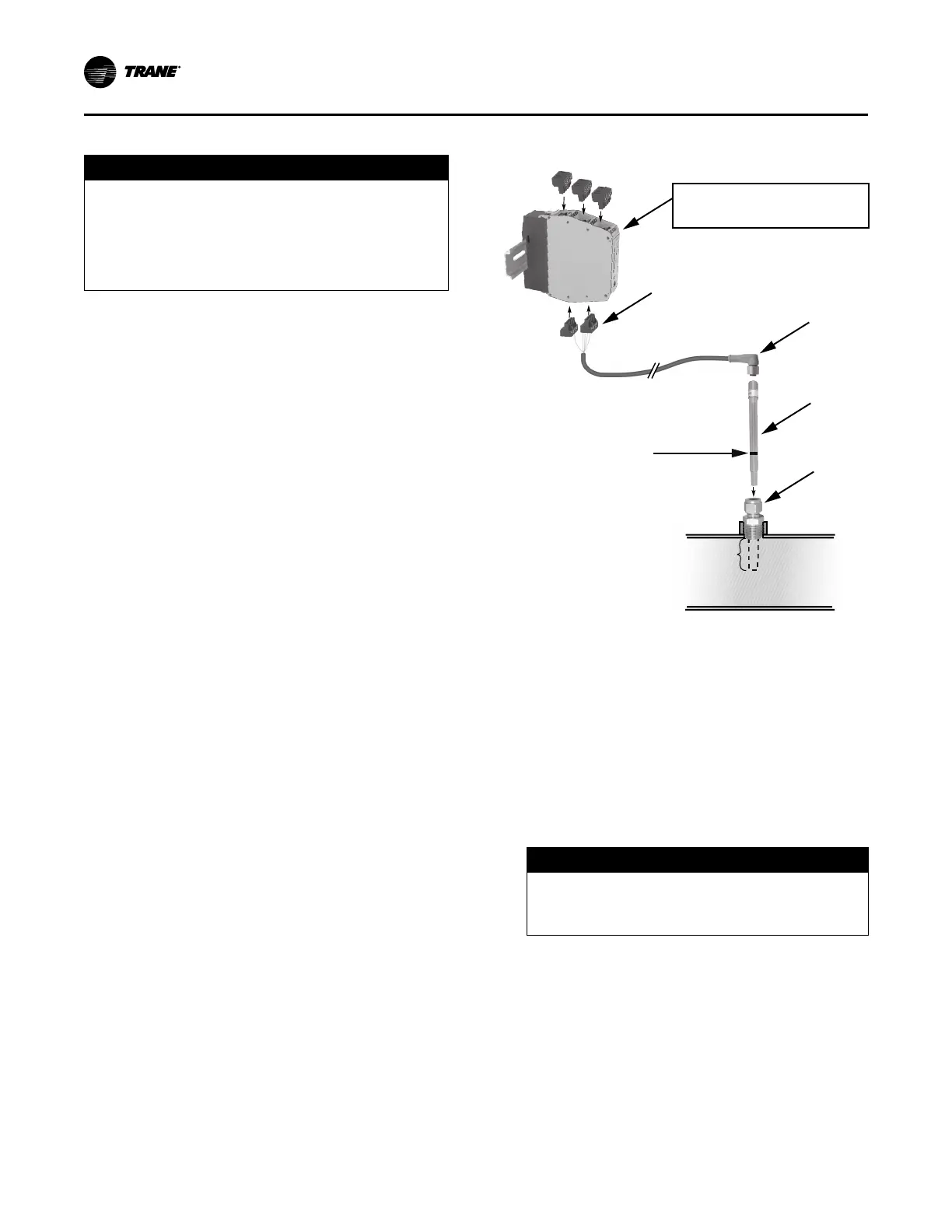
Figure 13. Installation of ifm efector flow detection
controller and sensor
If factory-provided,
located in control panel.
Do NOT insert more than
3.5 in. (8.9 cm) of the
probe length into the pipe.
4
3
2
1
Use a marker to draw a line
on the probe at 3.5 in. (8.9 cm)
from the probe end.
1. Mount the 1/2-in. NPT adapter in a horizontal or vertical
section of pipe. The maximum distance from the control
panel must not exceed 29.5 ft (9 m) (see item labeled
“1” in the preceding figure). Allow at least five pipe
diameters straight run of pipe upstream of the sensor
location, and three pipe diameters straight run of pipe
downstream of the sensor location.
Note: In the case of a horizontal pipe, mounting the
sensor in the side of the pipe is preferred. In the
case of a vertical pipe, mounting the sensor in a
place where the water flows upwards is
preferred.
NOTICE
Overtightening!
Do not exceed torque specifications as it could
result in equipment damage.
2. Insert the flow sensor probe (see item labeled “2” in the
preceding figure) through the 1/2-in. NPT adapter so
that 3 to 3.5 in. (7.6 to 8.9 cm) of the probe’s length
extends into the pipe. Tighten the 1/2-in. NPT adapter
as needed to prevent leakage and keep the probe from
backing out under pressure. Do NOT exceed 40 ft·lb
(54.2 N·m) of torque on the fitting. Sensor damage
can occur if it is overtightened.
Installation: Water Piping