CDHH-SVX003C-EN
87
• Boxes indicate control actions such as turning on
relays, or moving the inlet guide vanes.
• Smaller cylinders under the main cylinder indicate
diagnostic checks.
• Text outside a box or cylinder indicates time-based
functions.
• Solid double arrows indicate fixed timers.
• Dashed double arrows indicate variable timers.
Start-up Sequence of Operation—Wye-
delta
Logic circuits within the various modules will determine the
starting, running, and stopping operation of the chiller.
When operation of the chiller is required, the chiller mode is
set at “Auto.” Using customer-supplied power, the chilled
water pump relay is energized and chilled water flow must
be verified within 4 minutes and 15 seconds, at the same
time the oil vent line valve is opened. The controller
decides to start the chiller based on the differential to start
setpoint. With the differential to start criteria met, the
controller then energizes condenser water pump relay with
customer-supplied power (refer to the following figure).
Based on the Restart Inhibit function and the Differential to
Start setpoint, the oil and refrigerant pump is energized,
and the oil vent line valve is closed to the minimum
position. The oil pressure must be at least 12 psid
(82.7 kPaD) for 60 continuous seconds and condenser
water flow verified within 4 minutes and 15 seconds for the
compressor start sequence to be initiated. After the
compressor starts, the oil vent line valve begins to open; it
can take between 15 and 30 minutes to fully open
depending on the chiller running conditions.
The compressor motor starts in the “Wye” configuration
and then, after the compressor motor has accelerated and
the maximum phase current has dropped below 85 percent
of the chiller nameplate RLA for 1.5 seconds, the starter
transitions to the “Delta” configuration.
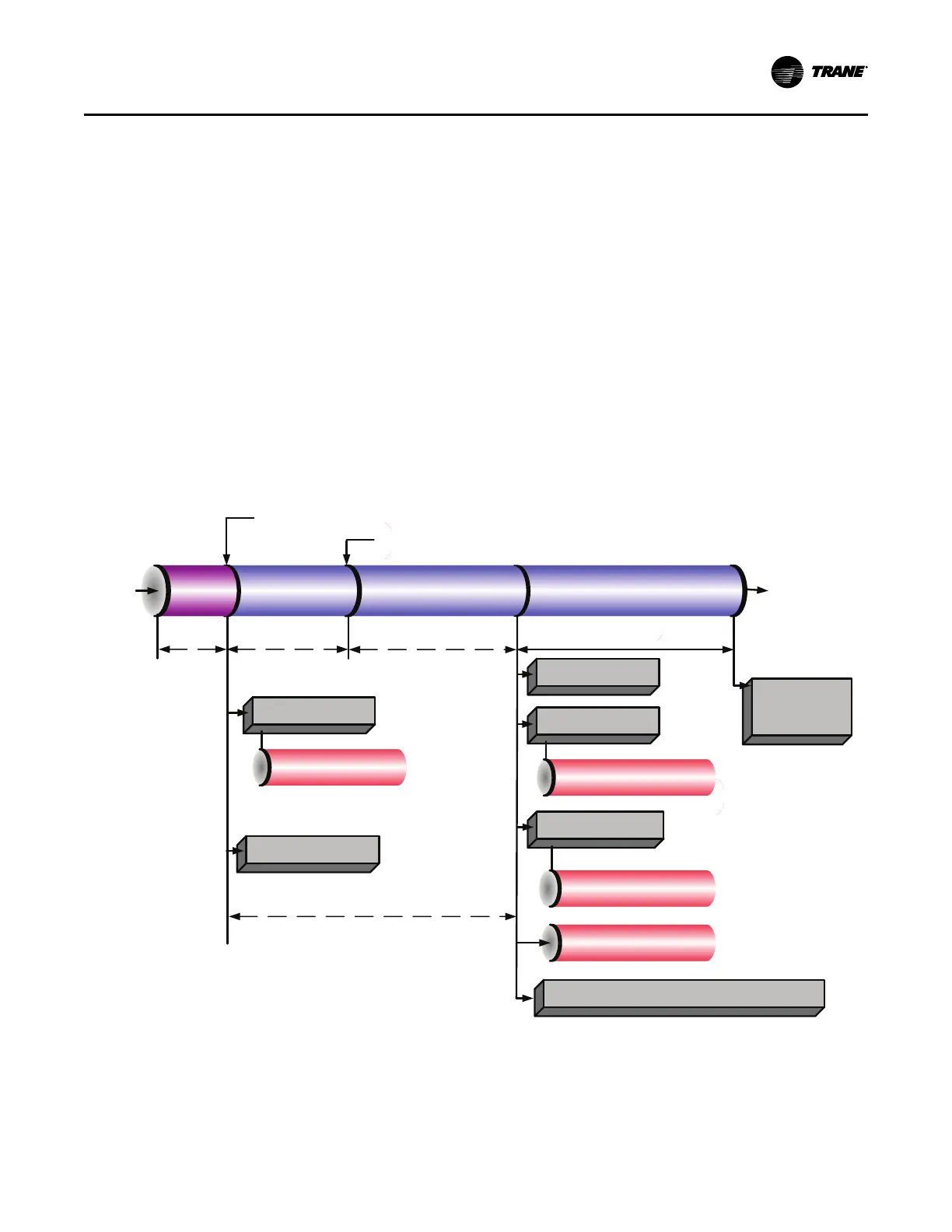
Figure 60. Sequence of operation: power up to starting
Enforce Start to Start Timer
(5 to 60 minutes)
Prelube (60 Se
c
onds)
Power
Applied
to
Controls
Last Chiller Mode
Was Auto
Auto
Call for Cooling
Waiting to Start
Starting
Compressor
Wait For Oil Temp to Rise Above
Sat Evap + 30F and 100F
Energize Evaporator
Water Pump Relay
Energize Condenser
Water Pump Relay
Energize Oil Pump Relay
Confirm Evaporator Water
Flow Within 4 mins 15
seconds (6 Sec Filter)
Confirm Condenser Water Flow
Within 4 mins 15 seconds
(6 Sec Filter)
Confirm 12 PSID Oil
Pressure
Within 3 mins
Check for High Vacuum
Lockout
Overdrive IGV Closed
Waiting to Start
Enforce Stop to Start Timer Using Values From
Real Time Clock (5-200 seconds 30 is Default)
Controller
Boot
Time
(15 Sec)
Enforce Power
Up Start Delay
Timer (0 to 30
minutes)
Initialize Oil Vent Line Valve to Minimum Open Position
(CVHH ONLY)
Open Oil Vent Line Valve
(CVHH ONLY)
Begin Oil Vent Line
Valve low limit
venting
(CVHH ONLY)
Now that the compressor motor is running in the “Delta”
configuration, the inlet guide vanes will modulate, opening
and closing to the chiller load variation by operation of the
stepper vane motor actuator to satisfy chilled water
setpoint. The chiller continues to run in its appropriate
mode of operation: Normal, Softload, Limit Mode, and so
on (refer to the following figure [running]). If the oil tank
temperature rises above the oil cooler setpoint while the
compressor is running, the oil cooler solenoid valve shall
be energized to cool the oil.
Note: For more information, refer to “Duplex Compressor
Sequencing,” p. 77.
Start-up and Shutdown