CDHH-SVX003C-EN
91
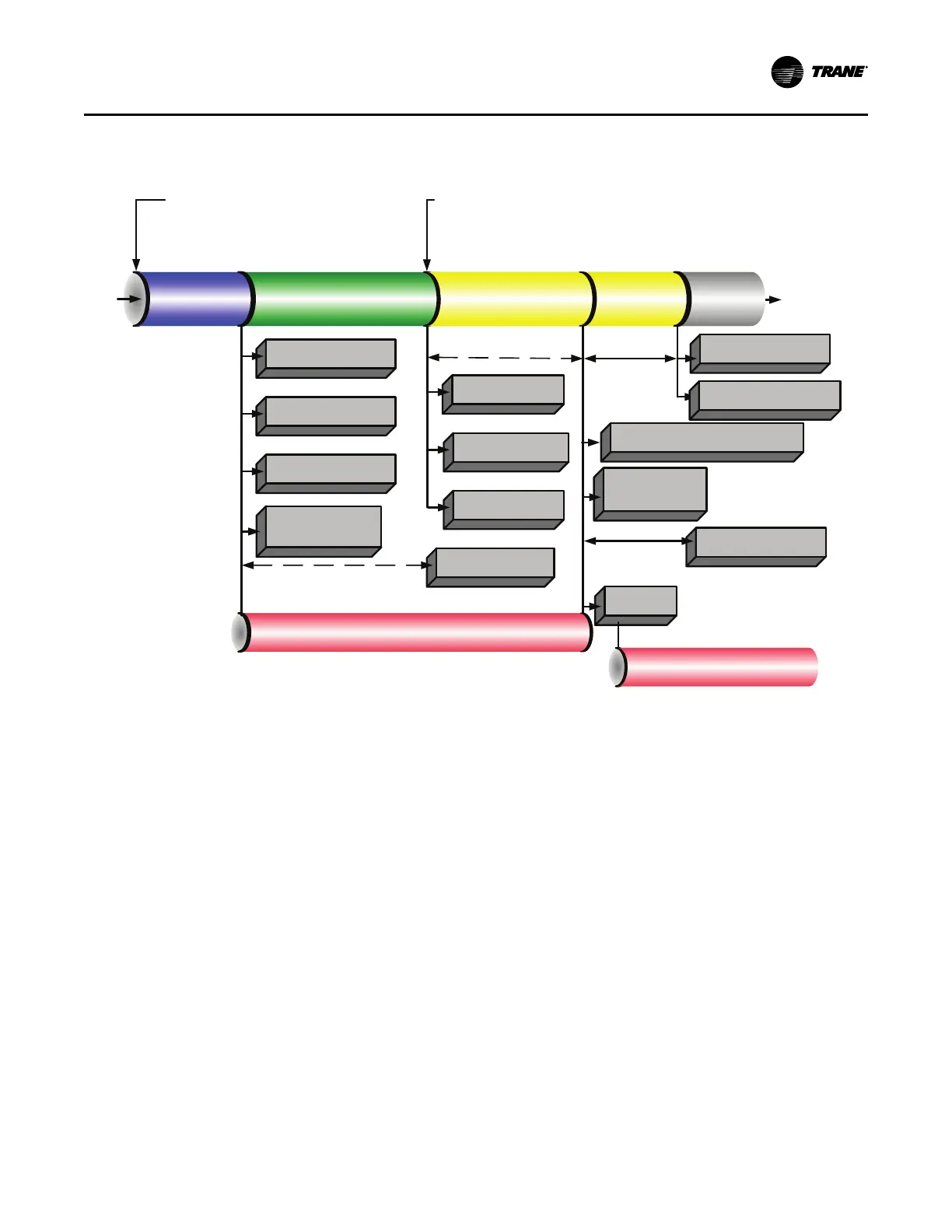
Figure 65. Sequence of operation: ice building: stopped to ice to ice building complete
Auto
Evap Entering
Water Temp Falls
Below the Ice
Termination
Setpoint
Run Inhibit
(Ice Building
Complete)
Running
(Ice Building)
Open IGV at Max Rate /
Max AFD Frequency
Close IGV /Min AFD
Frequency
Enforce All Limits and Running Mode Diagnostics
Ice Building Command:
1. Front Panel
2. Tracer
3. External Input
Energize Ice Building
Relay
Ignore Softloading and
Set CLS = 100%
De-Energize Ice Building
Relay
De-Energize Head Relief
Request Relay
Close IGV
(0-50 Seconds)
Starting
Compressor
Shutting
Down
Energize Head Relief
Request Relay
Head Relief Request Relay
Delay (1 to 60 Mins)
Preparing to
Shut Down
De-Energize Oil Pump
De-Energize
Compressor
Post Lube (3
Minutes)
Ignore Evap Pump Off
Delay Time For Ice
Building
De-Energize Evaporator
Water Pump Relay
De-Energize
Condenser
Water Pump Relay
Confirm No Compressor Currents
Within 8 Seconds
Run
Inhibit
Hold position of Oil Vent Line Valve
(CVHH ONLY)
Open Oil Vent Line Valve
(CVHH ONLY)
Begin Oil Vent Line
Valve low limit venting
(CVHH ONLY)
Hot Water Control
Occasionally, CenTraVac™ chillers are selected to provide
heating as a primary mission. With hot water temperature
control, the chiller can be used as a heating source or
cooling source. This feature provides greater application
flexibility. In this case, the operator selects a hot water
temperature and the chiller capacity is modulated to
maintain the hot water setpoint. Heating is the primary
mission and cooling is a waste product or is a secondary
mission. This type of operation requires an endless source
of evaporator load (heat), such as well or lake water. The
chiller has only one condenser.
Note: Hot Water Temperature Control mode does NOT
convert the chiller to a heat pump. Heat pump refers
to the capability to change from a cooling-driven
application to a heating-driven application by
changing the refrigerant path on the chiller. This is
impractical for centrifugal chillers as it would be
much easier to switch over the water side.
This is NOT heat recovery. Although this feature could be
used to recover heat in some form, a heat recovery unit has
a second heat exchanger on the condenser side.
The Tracer
®
AdaptiView™ provides the Hot Water
Temperature Control mode as standard. The leaving
condenser water temperature is controlled to a hot water
setpoint between 80°F and 140°F (26.7°C and 60.0°C).
The leaving evaporator water temperature is left to drift to
satisfy the heating load of the condenser. In this
application, the evaporator is normally piped into a lake,
well, or other source of constant temperature water for the
purpose of extracting heat. In Hot Water Temperature
Control mode, all the limit modes and diagnostics operate
as in normal cooling with one exception: the leaving
condenser water temperature sensor is an MMR diagnostic
when in Hot Water Temperature Control mode. (It is an
informational warning in the Normal Cooling mode.)
In the Hot Water Temperature Control mode, the
differential-to-start and differential-to-stop setpoints are
used with respect to the hot water setpoint instead of with
the chilled water setpoint. The control panel provides a
separate entry at the Tracer
®
AdaptiView™ to set the hot
water setpoint; Tracer
®
AdaptiView™ is also able to set the
hot water setpoint. In the Hot Water mode, the external
chilled water setpoint is the external hot water setpoint; that
is, a single analog input is shared at the 1K6-J2-5 to 6
(ground).
An external binary input to select external Hot Water
Control mode is on the EXOP OPTIONAL module 1K8
terminals J2-3 to J2-4 (ground). Tracer
®
AdaptiView™ also
Start-up and Shutdown