CDHH-SVX003C-EN
65
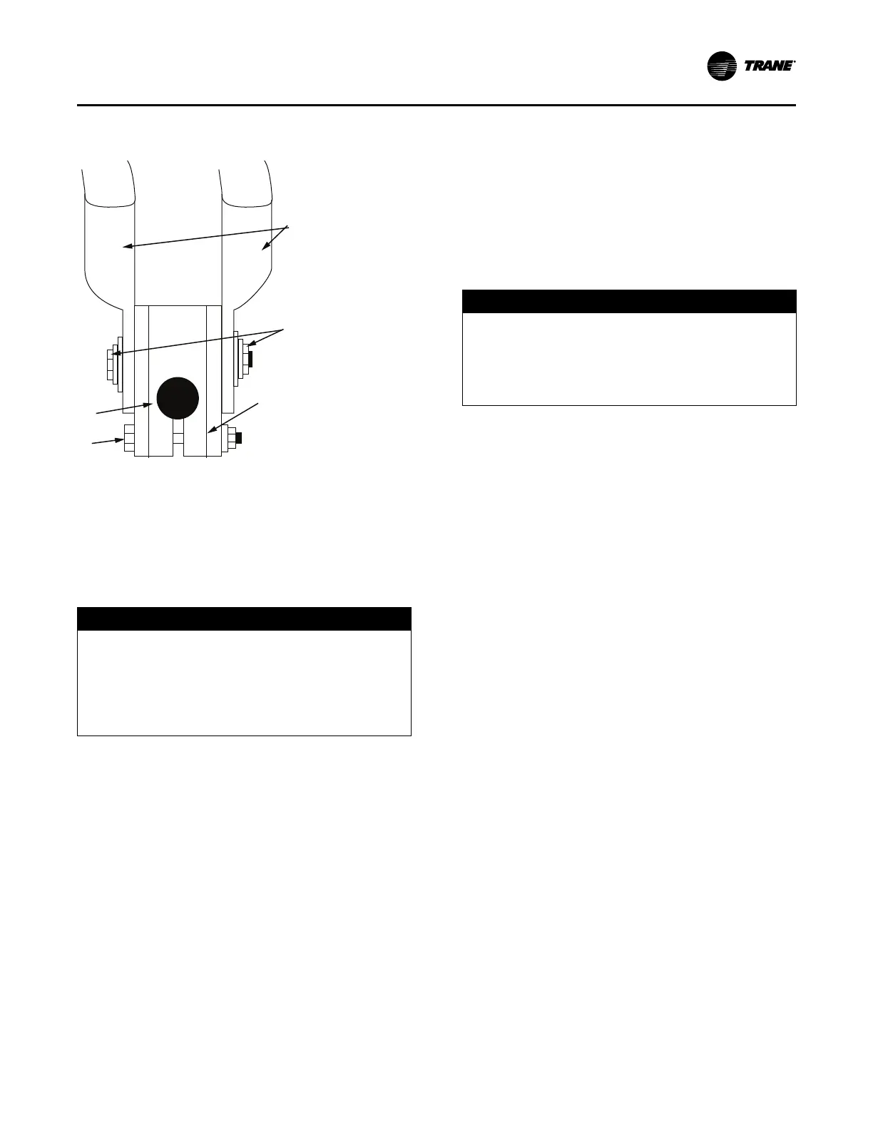
Figure 45. Terminal stud, clamp, and lug assembly
(600V and below)
1. Belleville washer
2. Terminal lugs
3. Terminal clamp
4. Motor terminal stud
5. Terminal mounting bolt
Bus Bars
NOTICE
Component Damage!
Failure to follow instructions below could cause an
electrical short which could result in component
damage.
Remove debris from inside the CPTR option
enclosure panel before turning the power on.
Bus bars and extra nuts are available as a Trane option.
Install the bus bars between the motor terminals when
using a starter that is:
• A low-voltage Adaptive Frequency™ Drive (AFD)
• Across-the-line
• Primary reactor/resistor
• Autotransformer
• Customer-supplied
Connect T1 to T6, T2 to T4, and T3 to T5.
Note: Bus bars are not needed in medium-voltage or high-
voltage applications since only three terminals are
used in the motor and starter.
Starter to Control Panel Wiring
The unit submittal includes the field wiring connection
diagram and the starter-to-control-panel connection
diagram (showing the electrical connections required
between the remote-mounted starter and the control
panel).
Note: Install separate conduit into the low voltage (30 volts)
section of the control panel.
When sizing and installing the electrical conductors for
these circuits, follow the guidelines listed. Use 14 AWG for
120V control circuits unless otherwise specified. For AWG/
MCM equivalents in mm
2
, refer to the table in “Electrical
Requirements,” p. 53.
NOTICE
Adaptive Frequency Drive (AFD)/Starter
Component Damage!
Failure to remove debris from inside the AFD/starter
panel could result in an electrical short and could
cause serious AFD/starter component damage.
Important: Maintain at least 6 in. (16 cm) between low-
voltage (less than 30V) and high-voltage
circuits. Failure to do so could result in
electrical noise that may distort the signals
carried by the low-voltage wiring, including the
inter-processor communication (IPC) wiring.
To wire the starter to the control panel, use these
guidelines:
• If the starter enclosure must be cut to provide electrical
access, exercise care to prevent debris from falling
inside the enclosure. Do NOT cut the Adaptive
Frequency™ Drive (AFD) enclosure.
• Use only shielded, twisted-pair wiring for the inter-
processsor communication (IPC) circuit between the
starter and the control panel on remote-mounted
starters.
Note: Recommended wire is Beldon Type 8760,
18 AWG for runs up to 1000 ft (304.8 m). For
AWG/MCM equivalents in mm
2
, refer to the
table in “Electrical Requirements,” p. 53. The
polarity of the IPC wiring is critical for proper
operation.
• Separate low-voltage (less than 30V; refer to the table
in “Trane-supplied Remote Starter Wiring,” p. 54)
wiring from the 115V wiring by running each in its own
conduit.
• When routing the IPC circuit out of the starter
enclosure, ensure that it is at least 6 in. (16 cm) from all
wires carrying a higher voltage.
Power Supply Wiring