CDHH-SVX003C-EN
31
Field-provided isolation valves for the evaporator and
condenser water lines should be installed upstream and
downstream of the heat exchangers, and be installed far
enough away from the chiller to also provide practical
service isolation for flow sensing devices, field
thermometers, flexible connectors, and any removable pipe
spools.
Ensure that the evaporator water piping is clear; check it
after the chilled water pump is operated but before initial
chiller start-up. If any partial blockages exist, they can be
detected and removed to prevent possible tube damage
resulting from evaporator freeze-up or erosion.
For applications that include an “infinite source” or
“multiple-use” cooling condenser water supply, install a
valved bypass “leg” (optional) between the supply and
return pipes. This valved bypass allows the operator to
short-circuit water flow through the cooling condenser
when the supply water temperature is too low.
Note: System refrigerant pressure differential must be
maintained above 3 psid (20.7 kPaD) at all times.
Failure to do so could result in operating problems.
Water Piping Connections
All standard units use grooved-pipe connections. These
are grooved-end NSP (Victaulic® style) pipe connections.
Flanged connections are optional.
Piping joined using grooved type couplings, like all types of
piping systems, requires proper support to carry the weight
of pipes and equipment. The support methods used must
eliminate undue stresses on joints, piping, and other
components, allow movement where required, and provide
for any other special requirements (i.e., drainage, etc.).
Note: If needed, plug-type sensor extension cables are
available for purchase from Trane Parts Service.
These sensor extension cables may be necessary if
the waterboxes are changed or if the temperature
sensors are moved out into the unit piping for better
mixed temperature readings.
Table 10. Water connection pipe sizes
Water
Passes
Shell Size
100 130 160 200 220 400 440
Evaporator Nominal Pipe Size (in.)
1-Pass 12 12 14 16 20 16 20
2-Pass 10 10 12 14 14 — —
3-Pass 8 8 10 12 12 — —
Condenser
Nominal Pipe Size (in.)
1-Pass 12 14 — 16 24 — 24
2-Pass 10 12 — 14 14 — —
Evaporator Metric Pipe Size (mm)
1-Pass DN300 DN300 DN350 DN400 DN500 DN400 DN500
2-Pass DN250 DN250 DN300 DN350 DN350 — —
3-Pass DN200 DN200 DN250 DN300 DN300 — —
Table 10. Water connection pipe sizes (continued)
Water
Passes
Shell Size
100 130 160 200 220 400 440
Condenser
Metric Pipe Size (mm)
1-Pass DN300 DN350 — DN400 DN600 — DN600
2-Pass DN250 DN300 — DN350 DN350 — —
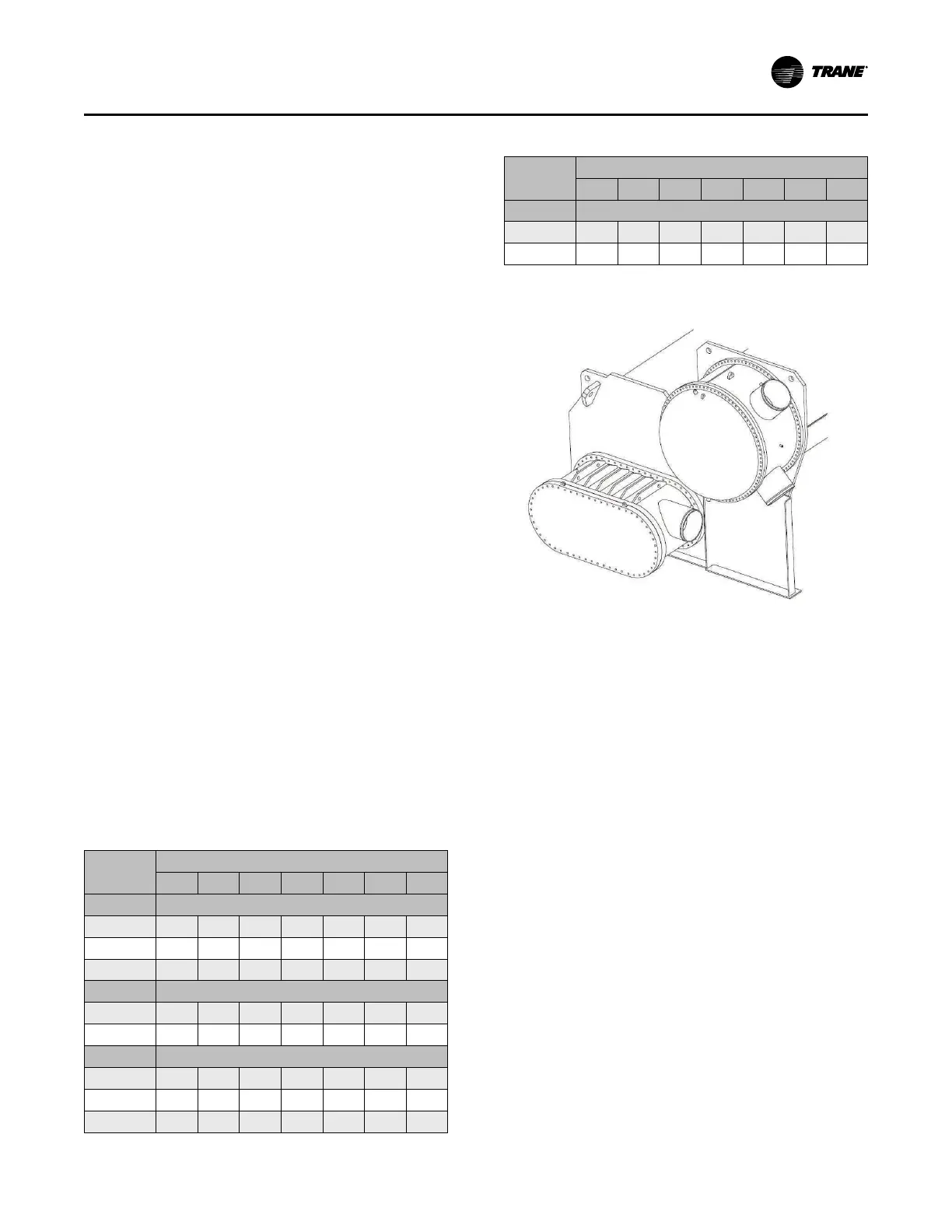
Figure 17. Typical grooved pipe connection
Waterbox Locations
If removal of waterboxes is necessary, refer to “Waterbox
Removal and Installation,” p. 111.
If the waterboxes on any of the shells are exchanged end-
for-end, be sure to reinstall them right-side up to maintain
the correct baffle arrangements. Use a new gasket with
each waterbox cover.
Three-pass waterboxes have lifting lugs on the top and
bottom. When reinstalling, ensure that the waterbox is
oriented the same way it as removed.
Grooved Pipe Coupling
A customer-supplied, standard flexible grooved pipe
coupling (Victaulic
®
Style 77 or equivalent) should be used
to complete the Victaulic
®
connection for both 150 psig
(1034.2 kPaG) and 300 psig (2068.4 kPaG) waterboxes.
When a flexible coupling such as this is installed at the
waterbox connections, other flexible piping connectors (i.e.,
braided-steel, elastomeric arch, etc.) are not usually
required to attenuate vibration and/or prevent stress on the
connections.
Installation: Water Piping