CDHH-SVX003C-EN
55
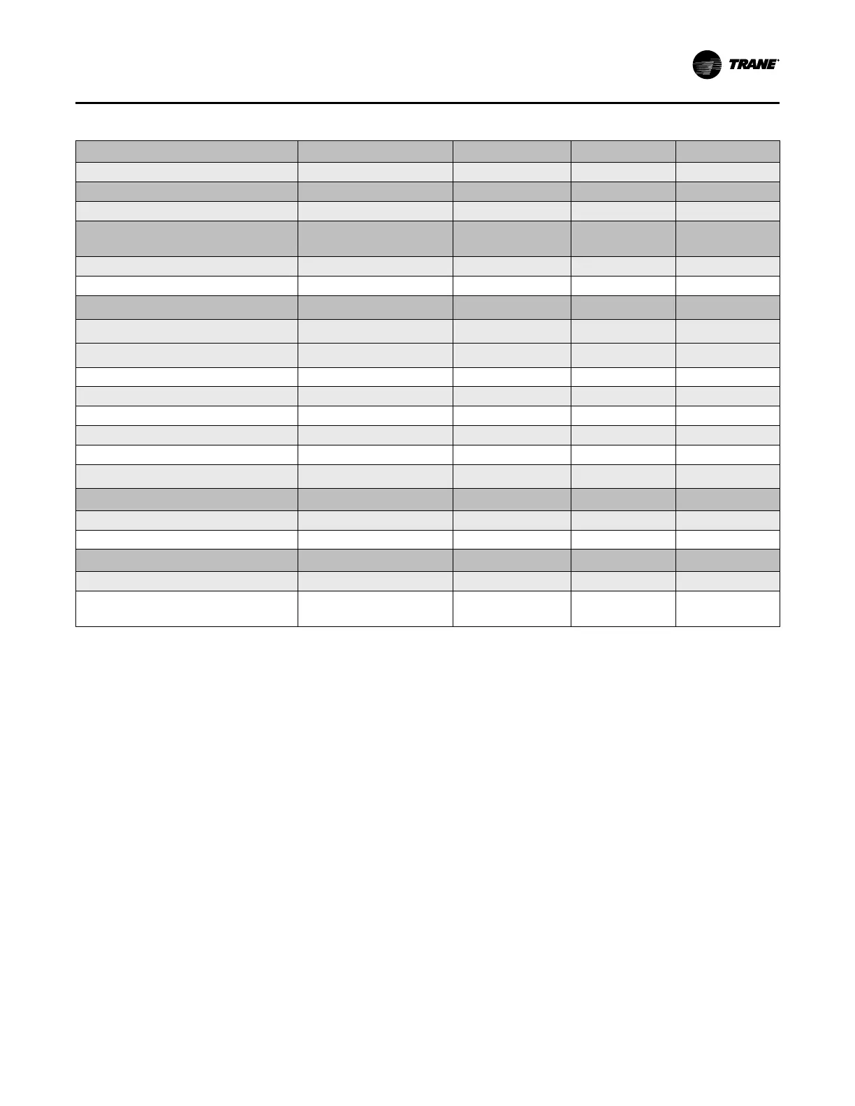
Table 17. Standard field power wiring requirements
Power Supply Wiring
to Starter Panel
Starter Panel
Terminals
3-Phase Line Voltage
L1, L2, L3, and Ground
(a)
Starter to Motor Power Wiring
Starter Motor
Remote Starter to Chiller Motor Junction Box
T1 through T6 T1 through T6
Power Supply Wiring to Unit-Mounted Control
Power Transformer
(CPTR Optional)
Control Power Transformer
Terminals
3-Phase Line Voltage
(b)
6Q1-1,3,5
Ground CPTR Panel GND
Starter to Control Panel
120 Vac Control Wiring
Starter Panel
Terminals
Unit Control Panel
Terminations
120 Vac Power Supply (from Starter to Control
Panel without optional CPTR)
2X8-2
2X8-G (Ground)
1X1-1, 1X1-12
1X1-30 (Ground)
120Vac Power Supply (from Starter to Control
Panel with optional CPTR)
2X8-1, 2X8-2,
2X8-G (Ground)
1X1-1, 1X1-12,
1X1-31(Ground)
High Pressure Cutout to Starter
2X8-4 1X1-4
1F1 Circuit Breaker to Starter 2X8-3 1X1-2
Oil Pump Interlock
2X8-7, 2X8-8 1X1-10, 1X1-21
Low-voltage Starter Oil/Refrigerant Pump Start
2X8-24 1X1-21
Medium-voltage Starter Oil/Refrigerant Pump Start
2X8-14 1X1-21
Low-voltage Oil/Refrigerant Pump Neutral
Medium-voltage Oil/Refrigerant Pump Neutral
2X8-25
2X8-15
1X1-16
1X1-16
Starter to Oil/Refrigerant Pump Junction Box
Starter Panel
Terminals
Oil/Refrigerant Pump
Junction Box
Low Voltage 3-Phase Pump Power
2X8-21, 2X8-22, 2X8-23 4X4-1, 4X4-2, 4X4-3
Medium Voltage 1-Phase Pump Power
2X8-12, 2X8-13 4X4-1, 4X4-4
Low Voltage Circuits
Less Than 30 Vac
Starter Panel
Terminals
Unit Control Panel
Terminations
Standard Circuits
Inter-processor Communications (IPC) Remote-
Mounted
(c) (d)
2K32-J3-3-4, or
2X8-19 to 21 if Present (Do NOT
Ground Shield at Starter)
1T2-J5-3-4
Shield Ground at
1X1-34 (GND) Only
2-wire with Gound
Comm Link
Notes:
1. All wiring to be in accordance with National Electrical Code (NEC) and any local codes.
2. For AWG/MCM equivalents in mm
2
, refer to the table in “Electrical Requirements,” p. 53.
3. Auxiliary equipment must be powered from other sources as the chiller control panel power supplies are sized for the chiller loads only.
(a)
Ground lug for a unit-mounted solid state starter or wye-delta starter is sized to accept 14 AWG solid to 8 AWG strand wire. If local codes require different lug size, it must be
field-supplied and -installed.
(b)
Refer to submittal and ship-with wiring schematics for voltage requirements.
(c)
Must be separated from 120 Vac and higher wiring.
(d)
The maximum distance a Trane–supplied remote starter can be placed from the chiller is 1000 ft (305 m).
Electrical Requirements