56
CDHH-SVX003C-EN
Customer-supplied Remote Starter Wiring
This information is applicable to Starter 1 for Compressor 1
as well as Starter 2 for Compressor 2. (For wire estimation
purposes, double check the following table as there are two
starters to be wired.)
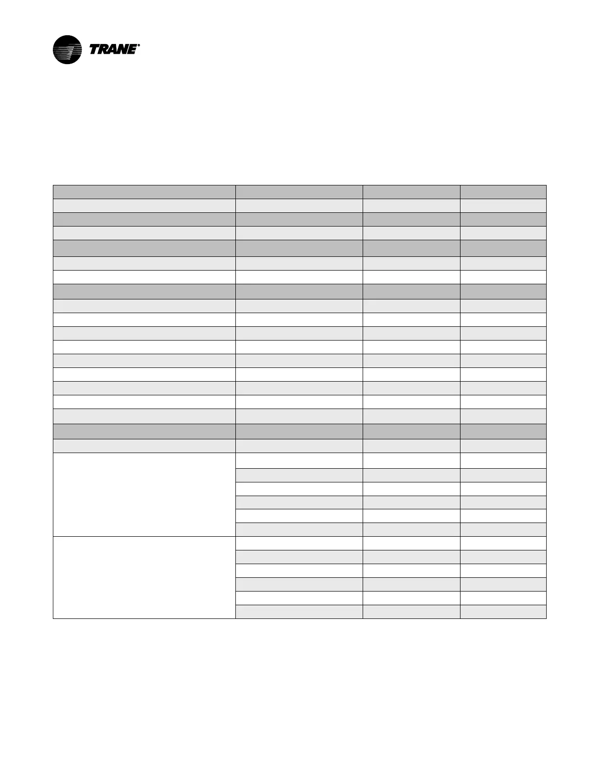
Important: The information in the table below is applicable
to Standard Starter or Drive Options. Consult
As-Builts, Submittal and/or consult Tech
Support for Sales orders with design special
drives and starters.
Table 18. Standard customer-supplied remote field wiring requirements
Power Supply Wiring to Starter Panel
Starter Panel Terminals
Starter by Others 3-phase Power Wiring See Starter by Others Schematic
Starter to Motor Power Wiring
Starters Motor
Remote Starter to Chiller Motor Junction box
(a)
T1 through T6 Terminals T1 through T6 Terminals
Power Supply Wiring to Unit-Mounted Control Power
Transformer (CPTR)
Control Power Transformer Terminals
3-Phase line voltage
(b)
6Q1-1,3,5
Ground CPTR Panel GND
Starter to Control Panel 120 Vac Control Wiring
Starter Panel Terminals
Unit Control Panel
Terminations
Power from Control Panel 1F1 5X12-3 1X1-2
Neutral from Control Panel 5X12-2 1X1-13
Ground from Control Panel 5X12-G 1X1-31
Interlock Relay Signal
5X12-4 1K23 J10-1
Start Contactor Signal
5X12-5 1K23 J8-1
Oil Pump Interlock
5X12-7, 5X12-8 1X1-10, 1X1-21
Run Contactor Signal
5X12-10 1K23 J6-1
Transition Complete
5X12-14 1K23 J12-2
Solid State Starter Fault
(c)
5X12-12
5X12-11
1K13 J2-2
1K13 J2-1
Low Voltage Circuits less than 30 Vac
Starter Panel Terminals
Unit Control Panel
Terminations
Standard Circuits
Current Transformers (refer to table in “Current Transformer
and Potential Transformer Wire Sizing,” p. 57) (Required)
(d)
5X12-19 1K23 J7-1
Note: Phasing Must be
Maintained
5X12-20 1K23 J7-2
5X12-21 1K23 J7-3
5X12-22 1K23 J7-4
5X12-23 1K23 J7-5
5X12-24 1K23 J7-6
Potential Transformers (Required)
5X12-25 1K23 J5-1
5X12-26 1K23 J5-2
5X12-27 1K23 J5-3
5X12-28 1K23 J5-4
5X12-29 1K23 J5-5
5X12-30 1K23 J5-6
Notes:
1. All wiring to be in accordance with National Electrical Code (NC) and any local codes.
2. For AWG/MCM equivalents in mm
2
, refer to the table in “Electrical Requirements,” p. 53.
3. Starter by Others Specification available from your local Trane sales office.
(a)
Wires, lugs, and fuses/breakers are sized based on National Electric Code (NEC) [NFPA 70] and UL 1995.
(b)
Refer to submittal and ship-with wiring schematics for voltage requirements.
(c)
Solid State Starter Fault input is used with low- and medium-voltage, customer-supplied solid state starters only.
(d)
Must be separated from 120 Vac and higher wiring.