CDHH-SVX003C-EN
41
L =
0.214d
5
(P
2
0
– P
2
2
)
–
d * ln(P
0
/ P
2
)
fC
2
R
6f
ASHRAE Standard 15
• L = equivalent length of discharge piping, feet
• C
r
= rated capacity as stamped on the relief device in
SCFM (conversion: lb/min = SCFM * 0.0764)
C
r
= C value in lb/min from the preceding table
• f = Moody friction factor in fully turbulent flow
• d = inside diameter of pipe or tube, in.
• ln = natural logarithm
• P
2
= absolute pressure at outlet of discharge piping, psi
(atmospheric pressure)
• P
0
= allowed back pressure (absolute) at the outlet of
pressure relief device, psi
– If chiller uses a rupture guard:
P
0
= (0.15 P) + atmospheric pressure
– If chiller uses a rupture disk:
P
0
= (0.5 P) + atmospheric pressure
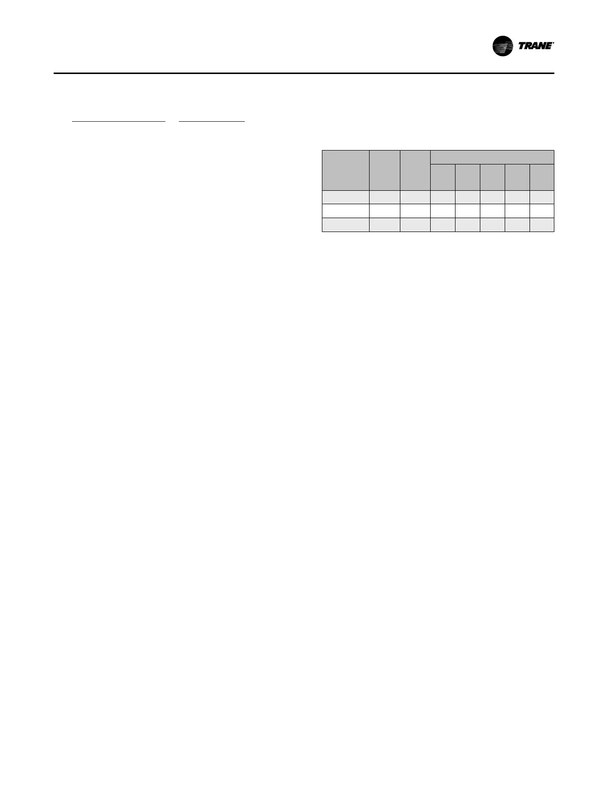
Table 14. “C” values used to determine rupture disk
vent line sizes (kg/s); for use with the
following figure
NTON
Evap.
Size
(EVSZ)
Cond.
Size
(CDSZ)
“C” Values for Unit Components
Total
“C”
Value
Evap.
Cond. Econ.
Oil
Tank
2000–2600 400M 440M 1.086 0.500 0.412 0.141 0.034
2800–3300 440M 440M 1.151 0.554 0.412 0.151 0.034
2800–3300 440X 440X 1.299 0.639 0.475 0.151 0.034
Notes:
1. Rupture disk diameter is 76.2 mm.
2. Use the total “C” value in the following figure to determine the vent line
pipe diameter.
3. If piping multiple rupture disks (multiple units) to a common vent line, first
determine the total “C” value for each unit, and then; add all “C” values
together and apply the result to the following figure .
4. The CDHH unit is a Duplex™ chiller and has (2) refrigerant circuits and
(2) relief devices. The "C" values shown in the table above are per
circuit values.
Vent Piping