Do you have a question about the Trocen AWC708C Plus and is the answer not in the manual?
Provides details on company and products via website and phone.
Lists contact methods for technical support and after-sales service.
Outlines the composition, installation, and usage of AWC708C PLUS.
Mentions the LaserCAD User Manual as a related document.
Introduces AWC708C PLUS as a motion controller for laser cutting/engraving.
Defines key terms like LaserCAD Software, TFT LCD Panel, and Wiring Board.
Instructions to confirm product and accessories upon receiving it.
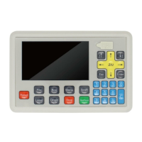
Describes the components of the control panel, including LCD, soft keys, and U disk slot.
Details the operation of function keys like Reset, File, Box, Menu, Shift, Laser, Origin, Stop, Start/Pause, Esc, Enter.
Explains the use of arrow keys for motion axis and cursor control, and Z/U keys for Z axis.
Describes the function of number keys for parameter modification and axis movement.
Shows a diagram of the wiring board and its layout.
Introduces port instructions for the wiring board.
Describes the laser power supply ports and their connections.
Details the motor drive control ports for connecting servo or step drivers.
Explains the limit signal inputs for axis limit detection.
Details the integral wiring diagram for hardware setup and connection.
Explains how to perform an input test to verify wiring accuracy and effectiveness.
Guides on setting the machine's origin point and modifying axis parameters.
Instructions on checking and modifying the motion axis direction based on key presses.
Explains how to calibrate the distance per pulse for motion axes.
Explains how to enable/disable hard limit parameters and set range parameters.
Displays control card type, date, time, and current file name.
Displays Max/Min laser power settings, time, status, and coordinates.
Covers file management, including selecting files and setting document parameters.
Details how to set document properties like repeat count, feed distance, and size.
Explains how to configure layer-specific parameters such as work mode and power settings.
Explains how to clear current and cumulative counts.
Guides on setting laser power while the machine is idle.
Covers managing files on a U disk, including work, config, and upgrade files.
Describes how to view and copy working files from a U disk to the main board.
Details how to copy configuration files from a U disk to the main board.
Explains the process of upgrading the system using files from a U disk.
Guides on saving the current mainboard configuration file to a U disk.
Covers managing multiple origin points for rapid switching and setting the current position as origin.
Explains how to use jog control for precise axis movement and adjusting distance per pulse.
Describes the cut box function used to determine origin point and graphics size.
Details how to reset Z, U, V, and W axes, and their functions.
Covers settings for space speed, cut jerk, space jerk, and acceleration.
Provides access to work mode, common parameters, axis speed, and rotate engraving settings.
Explains settings for go origin after reset, origin mode, go back position, count mode, feeding mode, and auto origin.
Details parameters like auto focus distance, key move speed, run box speed, and cut box speed.
Configures work speeds and home speeds for different axes (Z, U, V, W, XY).
Covers settings for rotary engraving, including head count, axis, pulse count, and diameter.
Allows configuration of CCD function, connection type, and data error check.
Details how to configure network settings, including IP address for connecting to a PC.
Explains how to change the system language to one of nine supported options.
Allows viewing system information, product ID, and user authorization code.
Covers detailed parameter settings for each axis (X, Y, Z, U, V, W).
Details settings for laser mode, TTL level, PWM frequency, max power, and water protection.
Allows configuration of foot switch, open protection, feed switch, and input valid level.
Enables or disables automatic resetting for XY, Z, U, V, and W axes upon power-on or reset.
Configures hard limit switches for each axis, noting that range parameters may suffice.
Manages settings for multi-laser head operation, including head count and spacing.
Enables or disables specific functions like Z-axis Autofocus and U-axis Feeding.
Details wiring for Panasonic A5 High Speed Pulse servo drivers.
Details wiring for Panasonic A5 Low Speed Pulse servo drivers.
Outlines basic setting parameters for Panasonic A5 series servo drivers.
Details wiring diagram and basic setting parameters for Yaskawa Sigma Series servo drivers.
Covers wiring diagrams and basic setting parameters for Delta A Series servo drivers.
Details wiring and basic setting parameters for Sanyo R Series servo drivers.
Covers wiring diagrams and basic setting parameters for Schneider 23A Lexium 23D Series servo drivers.
Provides wiring and basic setting parameters for Fuji ALPHA 5 Series servo drivers.
Details wiring and basic setting parameters for Mitsu J3 and E Series servo drivers.
| Model | AWC708C Plus |
|---|---|
| Supported Laser Types | CO2 Laser |
| Communication Interface | USB, Ethernet |
| Control Software | LaserCAD |
| Compatible Operating Systems | Windows XP/7/8/10 |
| Operating Voltage | 24V DC |
| Control Signal | PWM |
| Axes | 3 |
| File Format | DST, PLT, BMP, DXF, AI |
| Control System | DSP |
| Input Voltage | DC 24V |