C30HVRT Compressor Instruction Manual
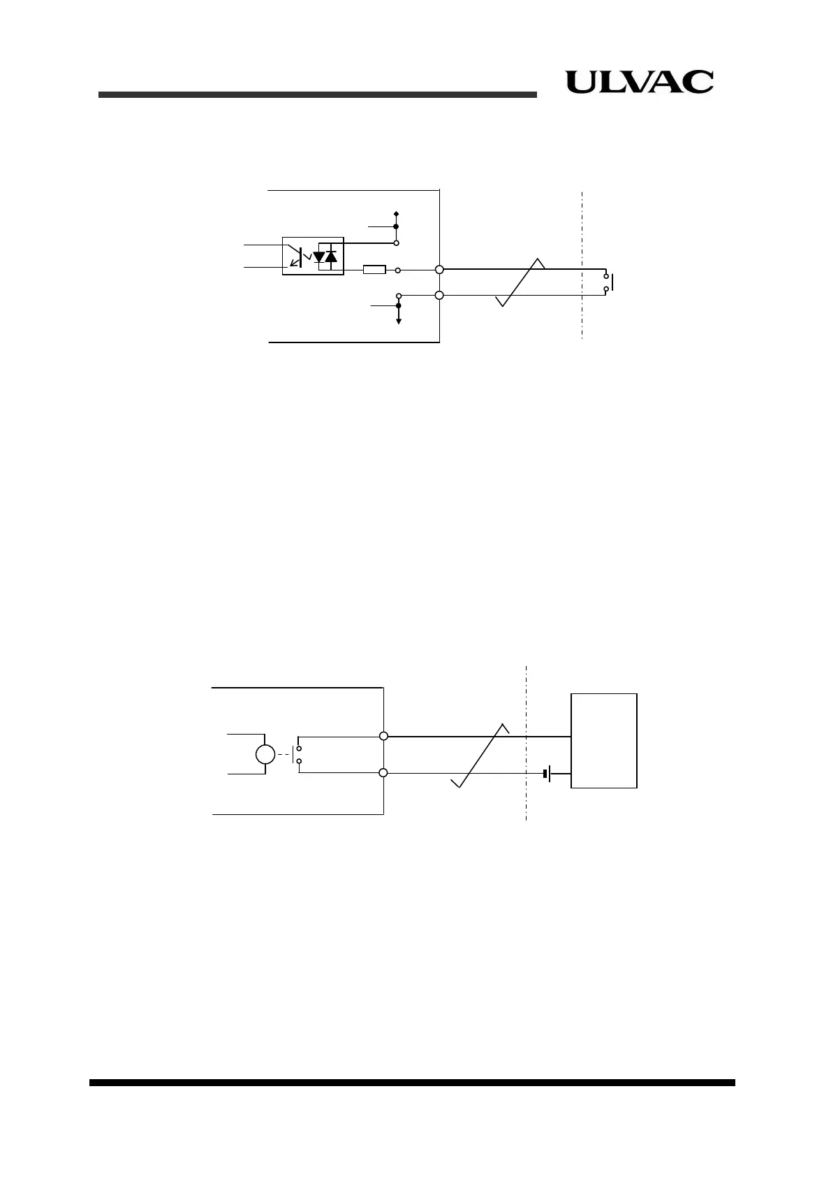
2.5.2 Remote input interface circuit
Figure 2-4 shows the remote input interface circuit.
Figure 2-4 Remote input interface circuit
Note that the 0VI is not connected to the ground line inside the compressor in the input
circuit. COM line is common with all other inputs.
2.5.3 Remote output interface circuit
Figure 2-5 shows the remote output interface circuit.
Each output is an isolated output contact. At the equipment side different power supply
can be used for each signal. However, considering that the wiring is sequence signal line,
it is recommended to use a DC24V power supply for all signals.
Since it is the contact output, the polarity of DC24V in Figure 2-5 can be reversed. Make
provisions for the interface circuit at the equipment side.
Figure 2-5 Remote output interface circuit
0VI
24VI
COM
SIG.
(Equipment side)
3.K
Photo Cou
le
24V
SIG1
SIG2
in
(Equipment side)
R
Relay
ULVAC CRYOGENICS INCORPORATED 2-7