UniPOS Fire Extinguishing Control Panel FS5200Е
Instruction Manual Page 12
Revision 7/06.12 of 63
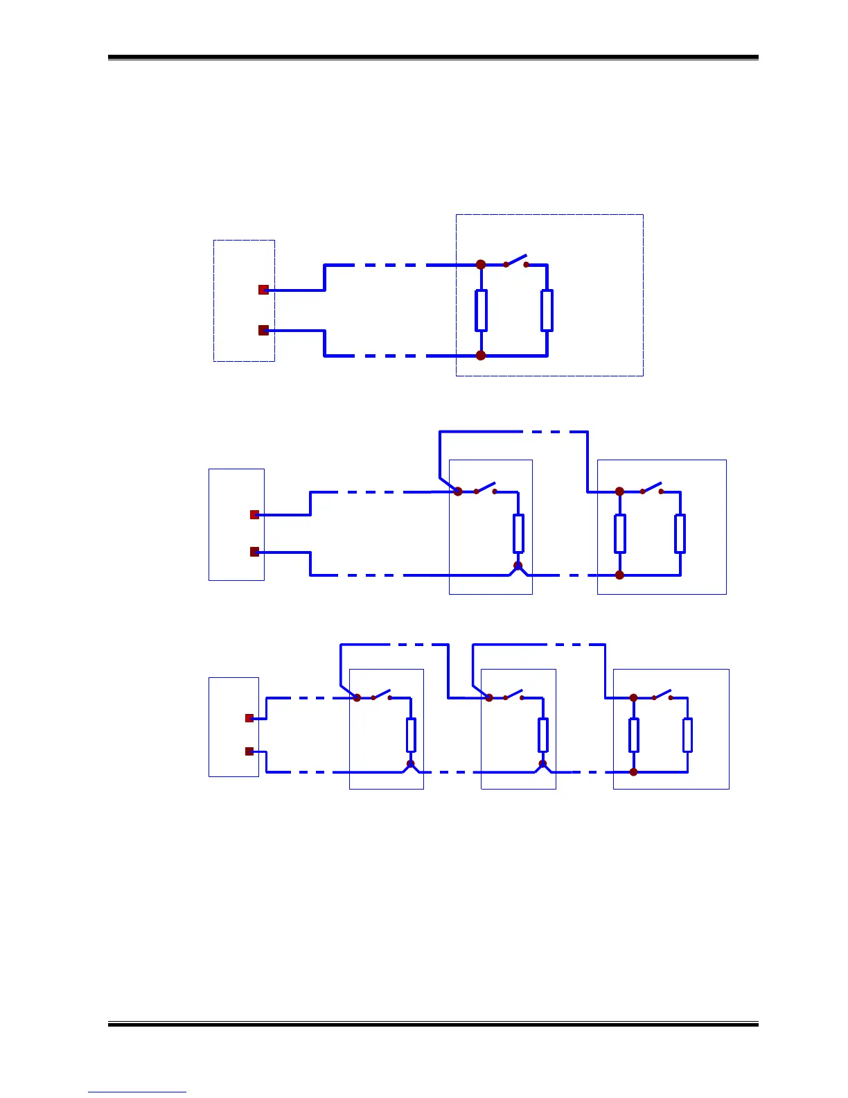
4.2.2. Description and mounting of devices to Manual Release input
Connect a two-wire line to the Manual Release input for connection with the manual release
buttons for extinguishing activation. It is possible to mount maximum three buttons. The line is
balanced and it is monitored for interruption and short circuit. Install resistors to the button terminals
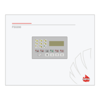
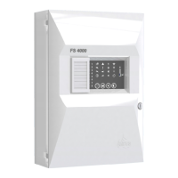
as shown in the connecting diagrams to monitor the condition. Install resistor 3k to the last button if 2
or 3 buttons are mounted (Drawing 3).
Connecting diagram with 1 button
Release
FS5200E
Button for manual
activation of the extinguishing
3k/
Manual
0.25W
1.5k/
0.25W
Connecting diagram with 2 buttons
Release
FS5200E
Button 1
Manual
1.5k/
0.25W
Button 2
3k/
0.25W
1.5k/
0.25W
Connecting diagram with 3 buttons
Release
FS5200E
Button2
Manual
1.5k/
0.25W
Button 3
3k/
0.25W
1.5k/
0.25W
Button 1
1.5k/
0.25W
Drawing 3
When the contact is closed the fire extinguishing control panel accepts the button to be active.
4.2.3. Description and mounting of devices to Mode Select input
Connect a two-wire line to the Mode Select input for connection with a switch to select the fire
extinguishing control panel mode – Manual-Automatic or Manual. The line is balanced and it is
monitored for interruption and short circuit. Install the two resistors to the switch terminals as shown in
the connecting diagram to monitor the condition.
When the contact is closed the fire extinguishing control panel accepts Manual Mode; when it is
opened – Manual-Automatic Mode. Output Open collector type is activated in Manual Mode. That
output could be used as switch indication, if this option is provided.