UniPOS Fire Extinguishing Control Panel FS5200Е
Instruction Manual Page 11
Revision 7/06.12 of 63
4.2.1. Description and mounting of devices to L1, L2 and L3 inputs
Connect a two-wire line at L1, L2 and L3 inputs for connection with the Fire detectors. The line
total resistance shall not exceed 100. The recommended wire section depending on the lines length
is:
To 500 m -cable 2 х 0.5 mm
2
To 1000 m -cable 2 х 1.0 mm
2
To 1500 m -cable 2 х.1.5 mm
2
It is recommended to make a check with a multicet before connecting the fire detecting line to the
fire extinguishing control panel. If the line is installed correctly (with mounted final resistor 3kΩ /
0.25W) between the plus and minus of the cable entering the fire extinguishing control panel the
measured resistance should be 3kΩ (+/-10%). Also when measuring both wires to ground the
multicet should show no connection or leakage.
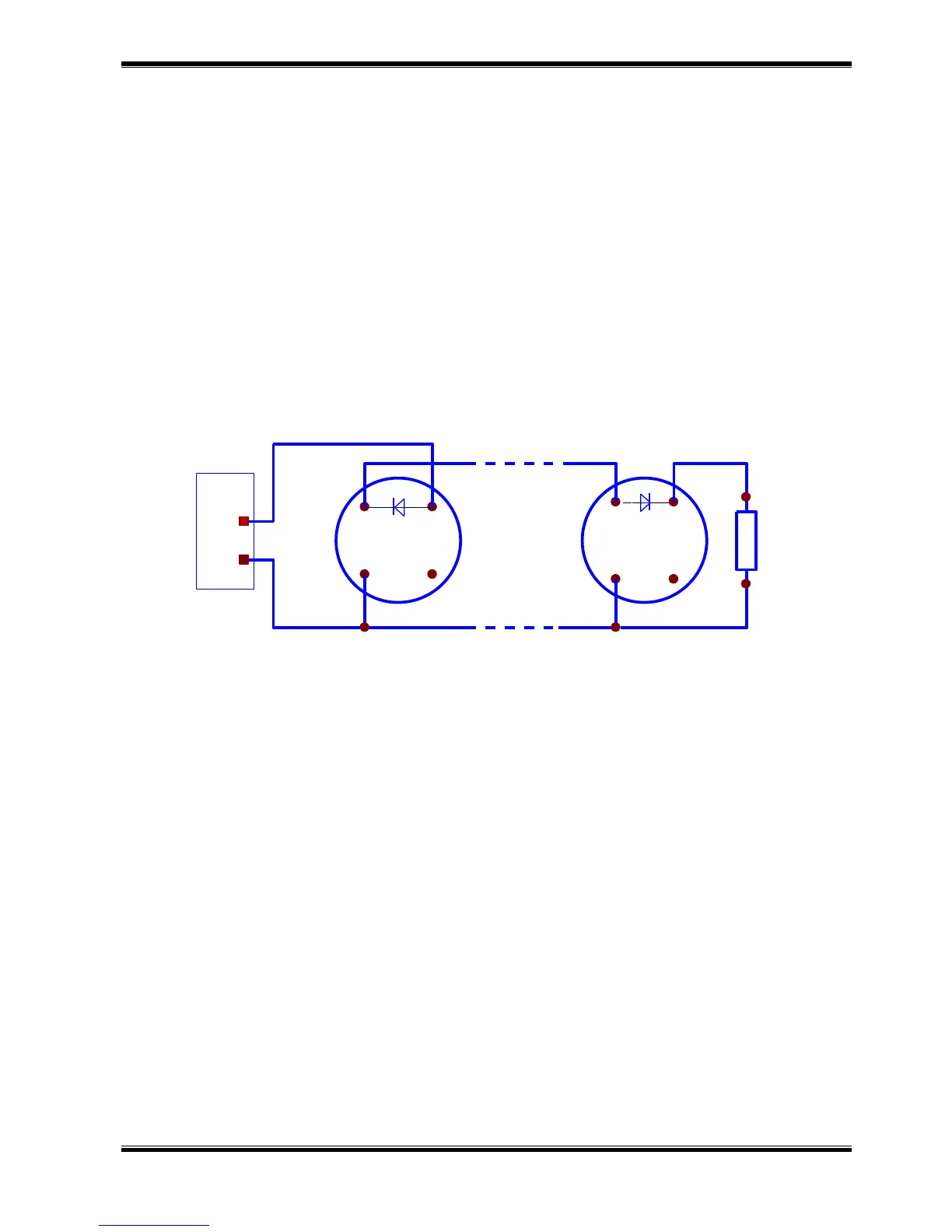
Make the connection to the terminals – “+ Lx -” (where “x” is the line number). Observe the shown
polarity (Drawing 2).
Drawing 2
Use automatic fire detectors FD3000 or FD8000 series or other compatible automatic fire
detectors. Mount resistor 3 kΩ / 0.25W on the last fire detector in the line.
Mount diodes, for example 1N5819 or similar in the shown direction if you are to use the fire
extinguishing control panel function to register Fault condition – removed fire detector.
Maximum 32 fire detectors could be mounted to one line regardless of their type.
When mounting the fire detectors take into consideration the specific technical characteristics of
the fire detector with the fire extinguishing control panel parameters for the current threshold in the
different conditions. Change the current threshold from Set up menu.
Current thresholds in a line with default parameters for the conditions:
0÷3mA* - interruption
3÷12mA* - duty mode
12÷80mA* - fire condition
>80mA - short circuit
Mount fire detectors on Lines 1 and 2 in the premise where the extinguishing will be performed.
The first and the second line are in a logical dependence „I”; the fire extinguishing control panel enters
Fire condition stage II if only both lines are activated and the extinguishing algorithm is possible to be
executed.
Line 3 is only Fire detecting and it serves for fire protection of the adjoining premises to the
extinguished zone. When this line is activated it switches on the outputs for Fire condition stage I as
well as the common output for Fire condition. This line is not included in the extinguishing algorithm
logic. Line 3 can be assumed as a standard line of a Fire control panel.