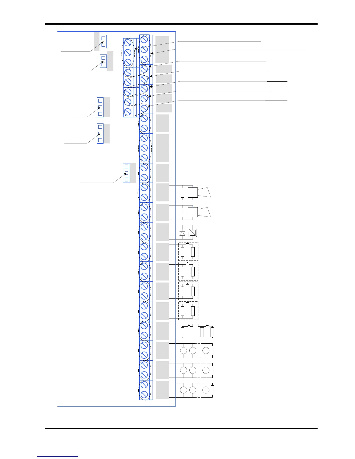
GND
NO NC C
REL Fault
Rele
Fire
+ S1 -
Sounder
+ S2 -
Sounder
+ -
Exting
Low
Press.
On/Off
Exting
Hold
Mode
Select
Manual
Release
+ L1 - + L2 -
+ L3 -
CAN term
RS485 term
NC NO NC NO
NC NO
A RS485 B
H CAN L
Rel
1ST
Rel
2ST
OK1
+28V
OK2
+28V
OK3
+28V
Jump (RS485)
Jump (CAN)
Jump Rel 1ST
Jump Rel 2ST
Jump relay Fire
Interface RS 485 (repeater, PC and other devices)
Interface CAN (join to system IFS7002)
Relay output in condition Fire Alarm Phase 1
Relay output in condition Fire Alarm Phase 2
Output Open Collector – Active in case of extinguisher leakage (+28V)
Output Open Collector – Active in case of extinguishind disable (+28V)
Output Open Collector – Active in manual mode (+28V)
Relay output in Fault Alarm condition
Relay output in Fire condition
3k 3k
Sounder Fire Alarm Phase 1
(28V/0,5A)
1N4004
Device Extinguishing
(28V/1,5A)
3k
1,5 k
3k
1,5k
3k
1,5k
3k
1,5k
Switch for monitoring
extinguisher leakage
Switch for extinguishing disable
Button for extinguishing delay
Switch mode manual/manual-automatic
3k
1,5k
1,5k
Buttons manual
extinguishing activation
3k
FD
FD
FD
3k
FD
FD
FD
3k
FD
FD
FD
Fire Alarm Line 1
FS5200E
Sounder Fire Alarm Phase 2
(28V/0,5A)
Fire Alarm Line 2
Fire Alarm Line 3
 Loading...