UniPOS Fire Extinguishing Control Panel FS5200Е
Instruction Manual Page 16
Revision 7/06.12 of 63
4.2.11. Description and mounting of devices to Rel 1
ST
and Rel 2
ND
outputs
Rel 1
ST
and Rel 2
ND
are potential free, relay outputs. The logic of the contact - Normally Open or
Normally Closed could be adjusted by means of a jumper. The outputs are not monitored. The
outputs are activated in Fire condition stage I and Fire condition stage II, respectively. The fire
extinguishing control panel provides the option to disable the activation of Rel 1
ST
and Rel 2
ND
outputs
from menu System functions > Disables > Disable Rel 1ST / Disable Rel 2ND.
4.2.12. Description and mounting of devices to Rel Fault output
Rel Fault is a potential free, relay output, as both relay contacts are possible Normally Open or
Normally Closed. The output is not monitored.
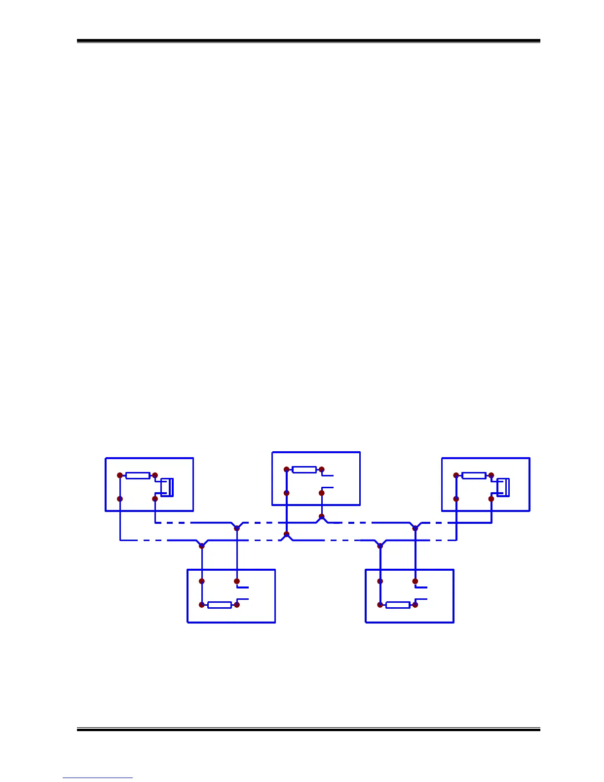
4.2.13. Description and mounting of devices to RS485 interface terminals
RS485 interface is designed to transmit information and to receive commands from FS5200R
repeater. The following connection configurations are possible:
One fire extinguishing control panel and one repeater
One fire extinguishing control panel and up to 6 repeaters
Up to 15 fire extinguishing control panels and 1 repeater
Up to 6 repeaters and up to 10 fire extinguishing control panels (If less than 6 repeaters
are installed they could be substituted by fire extinguishing control panels, i.e.
configuration of 3 repeaters and 13 fire extinguishing control panels, etc.)
FS5200R repeater receives information from all fire extinguishing control panels as it indicates
the occurred events by sound signaling, light indication and text messages. It is also possible a
remote fire extinguishing control panel to be reset.
RS485 interface could be used also for communication with other intelligent devices and PCs.
The connection between the devices along RS485 is parallel connection. Observe the
requirement potential A and B not to be crossed. The maximum distance between the end devices is
1000 meters. Jumper to shunt the line by 120 ohms has to be installed on the first and the last device
regardless the line length. On all other devices the jumper has to be removed (Drawing 11).