UniPOS Fire Extinguishing Control Panel FS5200Е
Instruction Manual Page 18
Revision 7/06.12 of 63
5.1.4. Access Level 4
Accessible for personnel trained and authorized by the Producer to repair the fire extinguishing
control panel and to modify the software.
Special means are required to enter this level.
5.2. Indications and buttons for control
Table 1 gives detail description of the indications for each status, Table 2 presents the basic
function of the control buttons. Appendix 1 shows the front panel of FS5200 with the indications and
buttons for control.
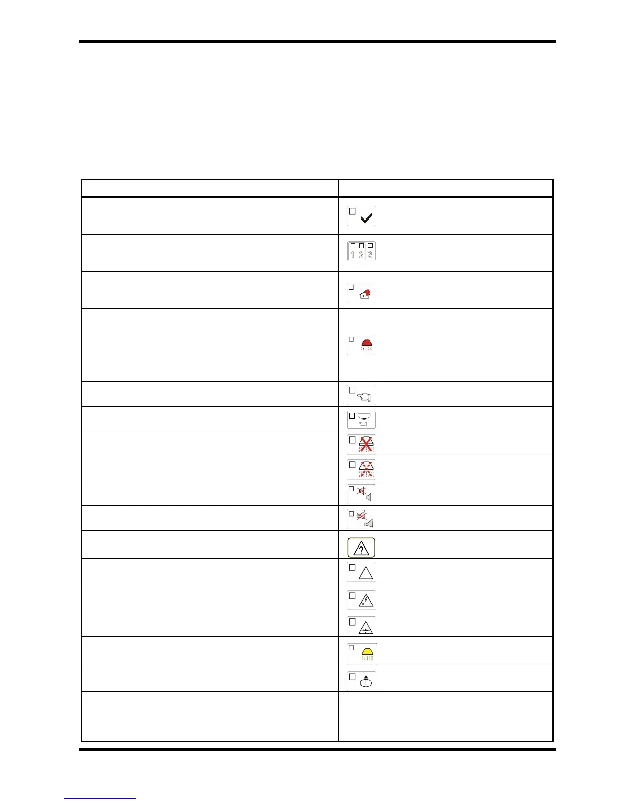
Table 1
Conditions of the fire extinguishing control panel
All conditions -
The fire extinguishing control panel is power
supplied
Indicator Power Supply –
continuous green light
Fire condition – Fire condition Stage I and Stage II
Individual indicators for
Fire condition in the fire detecting
lines
Fire condition – Fire condition Stage I
Common indicator Fire condition
Stage I –
continuous red light
Fire condition – Fire condition Stage II
Common indicator Fire condition
Stage II –
flashing red light during the
evacuation time and continuous
red light after the automated
extinguishing is switched on
Manual Mode – a signal for manual mode of
extinguishing control is given
Indicator Manual Mode -
continuous yellow light
Manual Mode – a signal for manual mode of
extinguishing control is given
Indicator Manual-Automatic Mode -
continuous yellow light
Disabled extinguishing – a signal disabling the
extinguishing is given
Indicator Disabled Extinguishing -
continuous yellow light
Extinguishing held – a signal holding the
extinguishing is given
Indicator Extinguishing Held - -
continuous yellow light
Fire Condition and Fault Condition – the sound
indication is suppressed
Indicator Stop Alarm - continuous
red light
Fire condition Stage I -
The fire condition stage I outputs are suppressed
Indicator Suppressed Outputs -
continuous red light
Fault condition - All faults except for Battery Low
Common indicator Fault Condition
- continuous yellow light
Fault condition – System Error and new
Configuration
Indicator System Error -
continuous yellow light
Fault condition – Fault in mains supply or backup
battery
Indicator mains Supply Fault -
continuous yellow light
Fault condition – fault condition in monitored line
Indicator Monitored Line Fault -
continuous yellow light
Fault condition – fault condition Low pressure in the
extinguishing installation
Indicator Low Pressure Fault -
continuous yellow light
Disabled component -
Disabled line or monitored output
Indicator Disabled Component –
continuous yellow light
Local sounder – discontinuous signal: 4
sound impulses for 1 s, followed by 1 s
break
Local sounder – continuous signal