9
vacon • 116 Safe Torque Off
Local contacts: http://drives.danfoss.com/danfoss-drives/local-contacts/
9.5 Connections
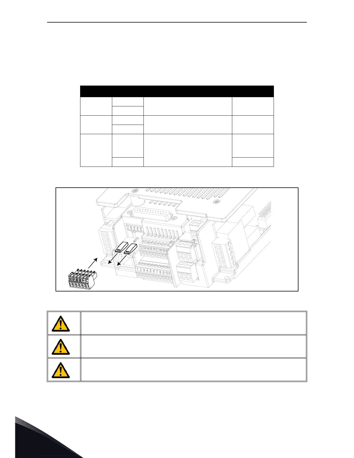
To make the STO function available and ready to be used, both the STO jumpers have to be removed.
They are located in front of the STO inputs to mechanically prevent the insertion of the STO connec-
tor. For the correct configuration, see the following table and the Figure 91.
Figure 91. Removing the STO jumpers.
The following examples show the basic principles for wiring the STO inputs and the STO output
feedback. Local standards and regulations must be always followed in the final design.
Table 47. STO connector and data signals.
Signal Terminal Technical information Data
STO1
S1
Insulated digital input 1
(interchangeable polarity)
24V ±20%
10...15 mA
G1
STO2
S2
Insulated digital input 2
(interchangeable polarity)
24V ±20%
10...15 mA
G2
STO feed-
back
F+
Insulated digital output for STO
feedback
(CAUTION! Polarity must be
respected)
24V ±20%
15 mA max.
F- GND
Make sure that the AC drive is switched off before cabling.
Disconnect both the STO jumpers to allow the cabling of the terminals.
When the STO function is used, the IP-class of the drive may not be reduced below
IP54. The IP-class of drive is IP66. It can be reduced by the wrong use of the cable
entry plates or the cable glands.

 Loading...


