Control unit vacon • 49
Local contacts: http://drives.danfoss.com/danfoss-drives/local-contacts/
5
5.1.5 Selection of terminal functions with dip switches
The VACON
®
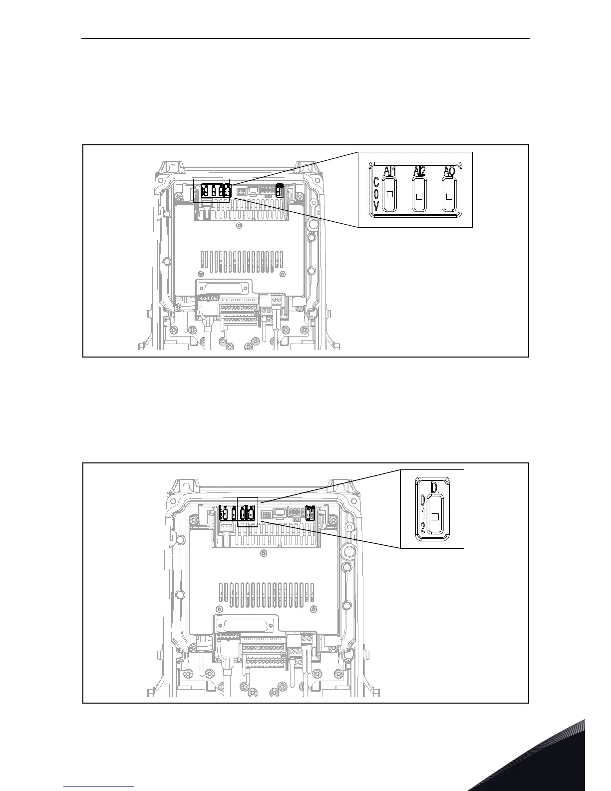
100 X drive embodies five so-called dip switches that allow for three functional selec-
tions each. The shadowed terminals in Table 23 can be functionally modified with the dip switches.
The switches have three positions: C, 0 and V. The switch in the position “C” means that the input
or the output has been set in current mode. The switch in the position “V” means voltage mode.The
middle position ”0” is for
Test mode. See Figure 32 to locate the switches and make appropriate
selections for your requirements. Factory defaults are: AI1 = V; AI2 = C, AO = C.
Figure 32. Dip switches for analogue inputs and analogue output.
5.1.6 Isolating digital inputs from ground
The digital inputs (terminals 8-10 and 14-16) on the standard I/O board can be isolated from ground
by setting the
dip switch to position ‘0’. The switch in the position “1” means that the common of
digital input has been connected to 24 V (negative logic). The switch in the position “2” means that
the common of digital inputs has been connected to ground (positive logic). See Figure 33. Locate
the switch and set it in desired position. Factory default is 2.
Figure 33. Digital inputs dip switch.

 Loading...


