Control unit vacon • 47
Local contacts: http://drives.danfoss.com/danfoss-drives/local-contacts/
5
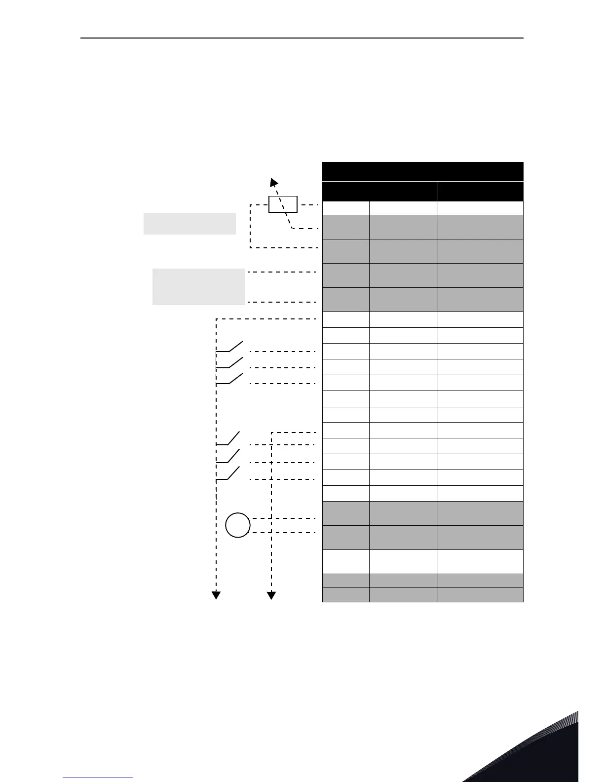
5.1.2 Standard I/O terminals
The terminals of the
Standard I/Os and the Relays are described below. For more information on
the connections, see chapter 7.
The terminals shown on shadowed background are assigned for signals with optional functions se-
lectable with DIP switches. See more information in chapter 5.1.5 and in chapter 5.1.6.
Table 23. Control I/O terminal signals and connection example.
Standard I/O
Terminal Signal
1 +10 Vref Reference output
2
AI1+
Analogue input,
voltage or current
3
AI1-
Analogue input com-
mon
4
AI2+
Analogue input,
voltage or current
5
AI2-
Analogue input com-
mon
6
24Vout 24V aux. voltage
7
GND I/O ground
8
DI1 Digital input 1
9
DI2 Digital input 2
10
DI3 Digital input 3
11
CM
Common for DI1-DI6
*
*. Can be isolated from ground, see
chapter 5.1.6.
12
24Vout 24V aux. voltage
13
GND I/O ground
14
DI4 Digital input 4
15
DI5 Digital input 5
16
DI6 Digital input 6
17
CM Common for DI1-DI6*
18
AO1+
Analogue output,
voltage or current
19
AO-/GND
Analogue output com-
mon
30 +24 Vin
24V auxiliary input
voltage
A RS485 Serial bus, negative
B RS485 Serial bus, positive

 Loading...


