Mounting vacon • 25
Local contacts: http://drives.danfoss.com/danfoss-drives/local-contacts/
3
3.5 Mounting
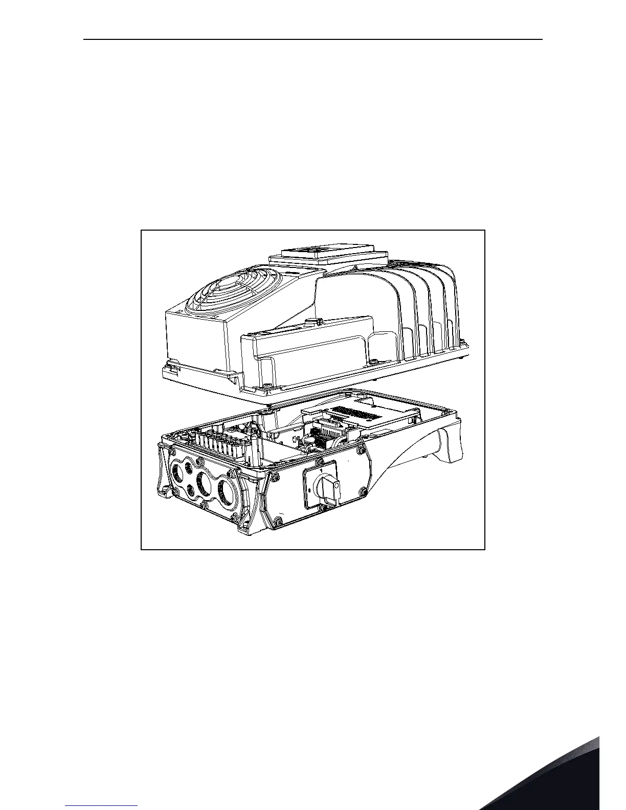
The drive consists of two main elements:
1. The terminal box that includes the power terminals and control board with the control terminals
and
2. The powerhead containing all the power electronics.
To install the drive, both parts need to be separated. The terminal box must be fixed first and all
cabling done. After this, the powerhead will be plugged on the terminal box and fixed with 4 (MM4
and MM6) or 6 (MM5) dedicated screws located on top side of the powerhead (see Figure 15.). In or-
der to guarantee specified IP protection, recommended fastening torque is 2-3 Nm. The screws
must be tightened crosswise.
Figure 15. Separation of modules(MM5 example).

 Loading...


