EasyManuals Logo

Vacon 100 X Installation, Technical And Maintenance Manual

Vacon 100 X
132 pages
To Next Page IconTo Next Page
To Previous Page IconTo Previous Page
Page #30 background imageLoading...
Page #30 background image
4
vacon • 28 Power cabling
Local contacts: http://drives.danfoss.com/danfoss-drives/local-contacts/
4. POWER CABLING
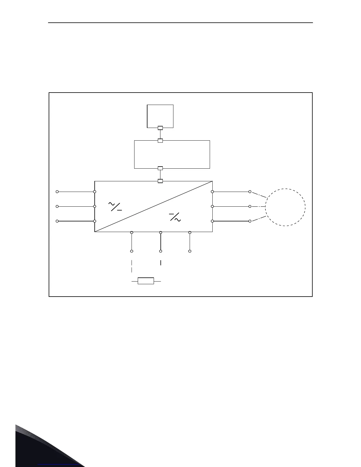
The mains cables are connected to terminals L1, L2 and L3 and the motor cables to terminals
marked with U, V and W. See principal connection diagram in Figure 17. See also Table 12 for the
cable recommendations for different EMC levels.
Figure 17. Principal connection diagram.
Use cables with heat resistance in accordance with the application requirements. The cables and
the fuses must be dimensioned according to the AC drive nominal OUTPUT current which you can
find on the rating plate.
U/T1
V/T2
W/T3
M
L1
L2
L3
DC+
R-
DC-
Keypad
Control unit
Power unit

Table of Contents

Other manuals for Vacon 100 X

Questions and Answers:

Question and Answer IconNeed help?

Do you have a question about the Vacon 100 X and is the answer not in the manual?

Vacon 100 X Specifications

General IconGeneral
BrandVacon
Model100 X
CategoryController
LanguageEnglish

Related product manuals