5
vacon • 52 Control unit
Local contacts: http://drives.danfoss.com/danfoss-drives/local-contacts/
5.2.2 Prepare for use through RS485
1
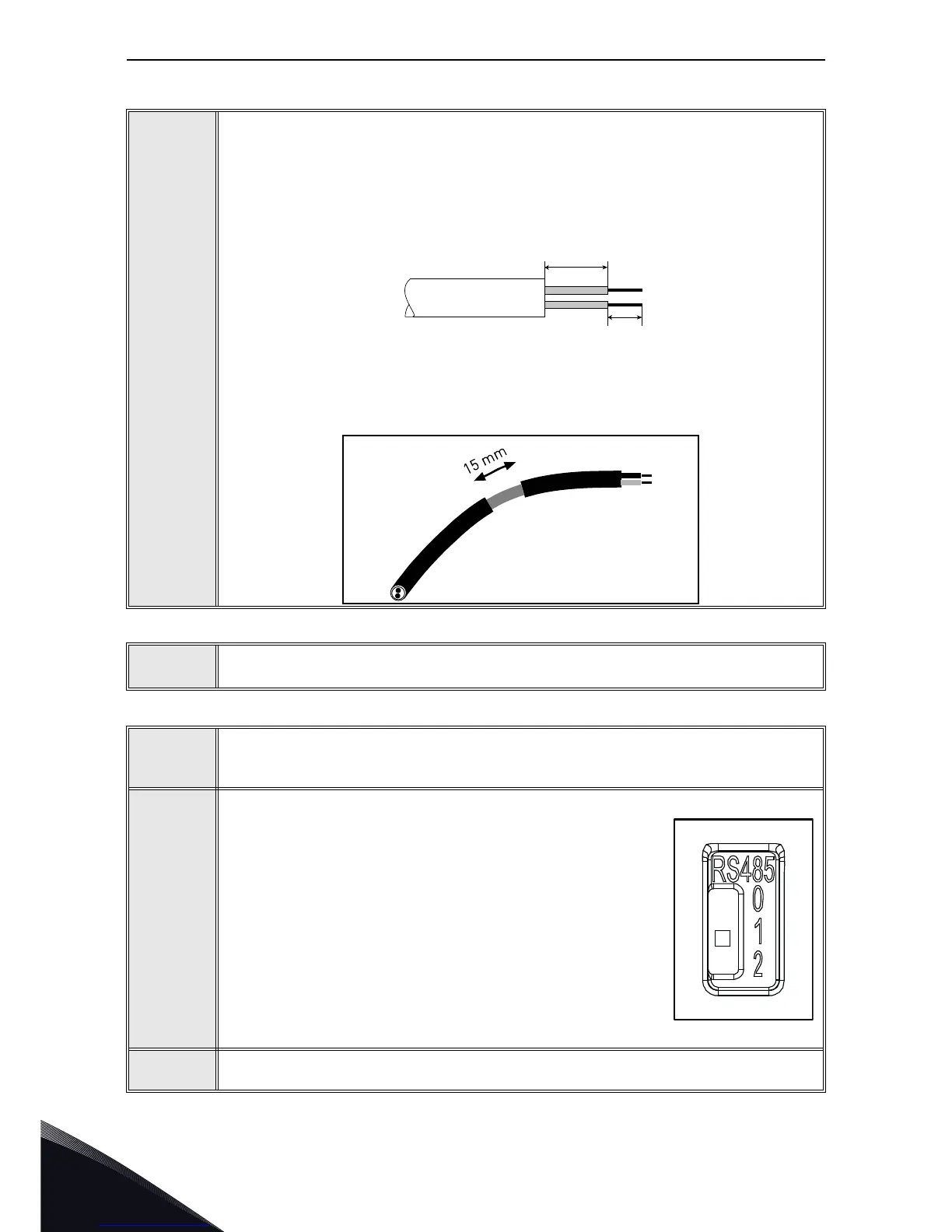
Strip about 15 mm of the RS485 cable (see specification on page 53) and cut off the
grey cable shield. Remember to do this for both bus cables (except for the last
device).
Leave no more than 10 mm of the cable outside the terminal block and strip the
cables at about 5 mm to fit in the terminals. See picture below.
Also strip the cable now at such a distance from the terminal that you can fix it to the
frame with the grounding clamp. Strip the cable at a maximum length of 15 mm. Do
not strip the aluminum cable shield!
2
Then connect the cable to its appropriate terminals on VACON
®
100 X AC drive stan-
dard terminal block, terminals A and B (A = negative, B = positive). See Figure 35.
3
Using the cable clamp included in the delivery of the drive, ground the shield of the
RS485 cable to the frame of the AC drive.
4
If VACON
®
100 X AC drive is the last device on the bus, the
bus termination must be set. Locate the DIP switches to the
top of the control unit (see Figure 32) and turn the right most
switch to position “1”. Biasing is built in the termination
resistor. See also step 6.
5
NOTE: When planning the cable runs, remember to keep the distance between the
fieldbus cable and the motor cable at a minimum of 30 cm.

 Loading...


