Electrical cabling and connections vacon • 99
Local contacts: http://drives.danfoss.com/danfoss-drives/local-contacts/
6
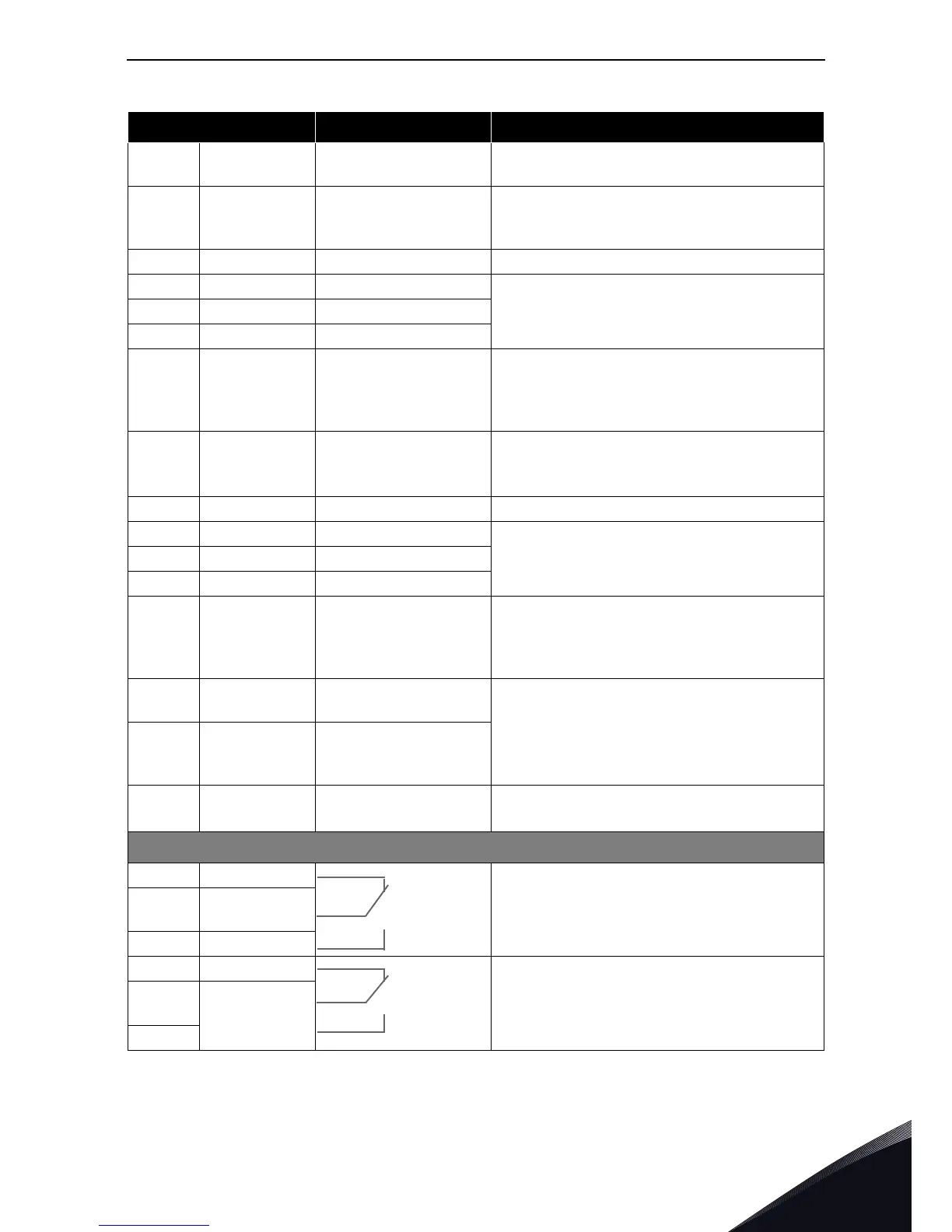
5 GND/AI2–
Analogue input
common
Differential input if not connected to ground;
Allows ±20 V differential mode voltage to GND
6
24 V
out
(bidirectional)
24 V auxiliary voltage
±15%, maximum current 250 mA
Can also be used as external power backup
for the control unit (and fieldbus)
7 GND I/O ground Ground for reference and controls
8 DIN1 Digital input 1
R
i
= min. 5 kΩ
18...30 V = "1"
9 DIN2 Digital input 2
10 DIN3 Digital input 3
11 CMA
Digital input common A
for DIN1, DIN2 and
DIN3.
Must be connected to GND or 24 V of I/O
terminal or to external 24 V or GND
Selection with jumper block X3 (see
page 102):
12
24 V
out
(bidirectional)
24 V auxiliary voltage Same as terminal #6
13 GND I/O ground Same as terminal #7
14 DIB4 Digital input 4
R
i
= min. 5 kΩ
15 DIB5 Digital input 5
16 DIB6 Digital input 6
17 CMB
Digital input common B
for DIB4, DIB5 and DIB6
Must be connected to GND or 24V of I/O
terminal or to external 24 V or GND
Selection with jumper block X3 (see
page 102):
18 AO1+
Analogue signal (+out-
put)
Output signal range:
Current 0(4)–20 mA, R
L
max 500 Ω or
Voltage 0—10 V, R
L
>1 kΩ
Selection with jumper block X6 (see
page 102):
19 AO1–
Analogue output
common
20 DO1 Open collector output
Maximum U
in
= 48 VDC
Maximum current = 50 mA
OPT-A2
21 RO1/1
Relay output 1
Max. switching voltage 250 VAC, 125 VDC
22 RO1/2 Max. switching current
8 A/24 VDC,
0.4 A/250 VDC
23 RO1/3 Min. switching load 5 V/10 mA
24 RO2/1
Relay output 2
Max. switching voltage 250 VAC, 125 VDC
25
RO2/2
RO2/3
Max. switching current
8 A/24 VDC,
0.4 A/250 VDC
26 Min. switching load 5 V/10 mA
Table 46. Control I/O terminal signals
Terminal Signal Technical information