6
vacon • 98 Electrical cabling and connections
Local contacts: http://drives.danfoss.com/danfoss-drives/local-contacts/
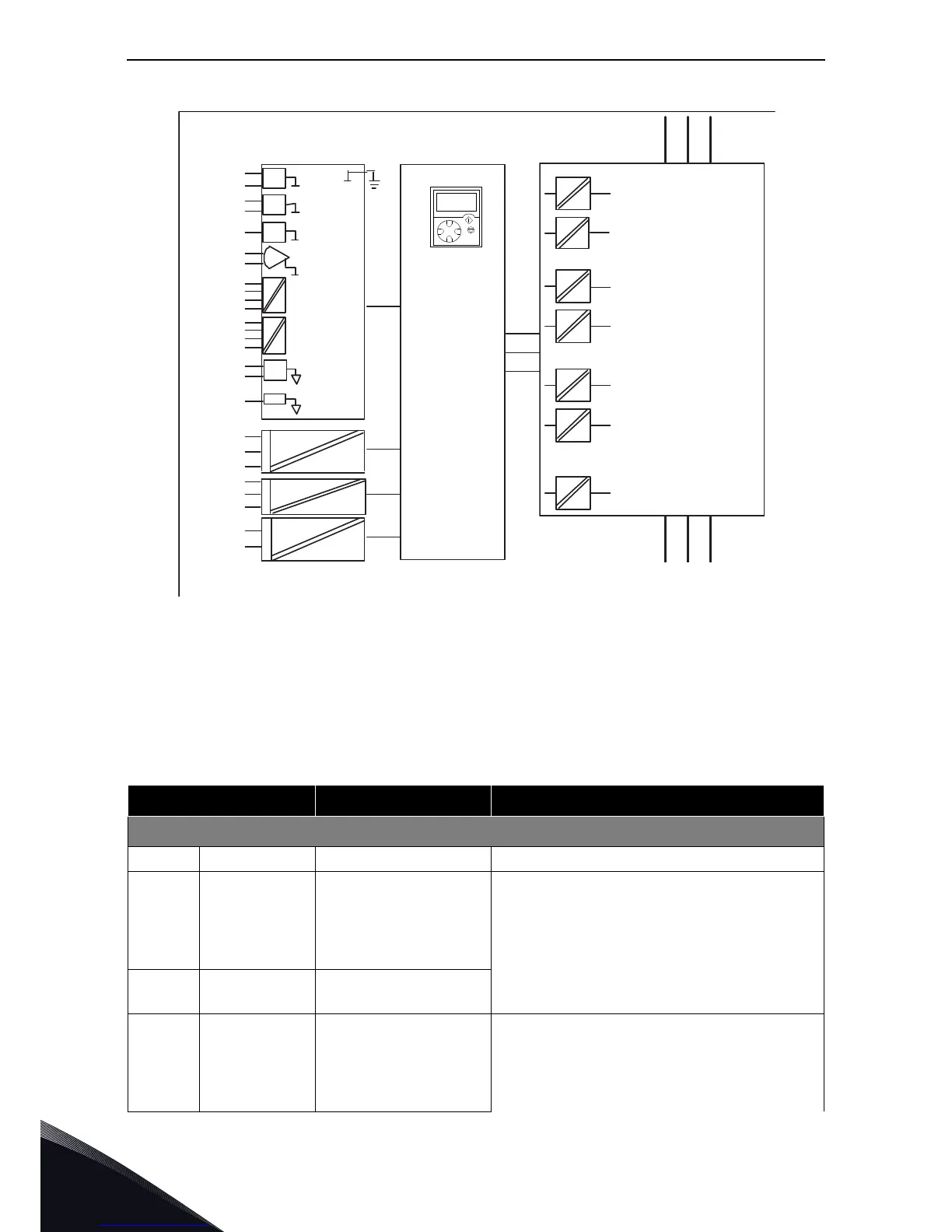
Figure 46. Galvanic isolation barriers
6.2.3 Control terminal signals
Table 46. Control I/O terminal signals
Terminal Signal Technical information
OPT-A1
1 +10 Vref Reference voltage Maximum current 10 mA
2AI1+
Analogue input,
voltage or current
Selection V or mA with jumper block X1 (see
page 102):
Default:0– +10 V (Ri = 200 kΩ)
(-10 V…..+10 V Joy-stick control, selected with a jumper)
0– 20 mA (Ri = 250 Ω)
3 GND/AI1–
Analogue input
common
Differential input if not connected to ground;
Allows ±20 V differential mode voltage to GND
4AI2+
Analogue input,
voltage or current
Selection V or mA with jumper block X2 (see
page 102):
Default:0– 20 mA (Ri = 250 Ω)
0– +10 V (Ri = 200 kΩ)
(-10 V…..+10 V Joy-stick control, selected with a jumper)