EasyManuals Logo

Vacon NX User Manual

Vacon NX
239 pages
To Next Page IconTo Next Page
To Previous Page IconTo Previous Page
Page #96 background imageLoading...
Page #96 background image
6
vacon • 94 Electrical cabling and connections
Local contacts: http://drives.danfoss.com/danfoss-drives/local-contacts/
6.2 Control unit
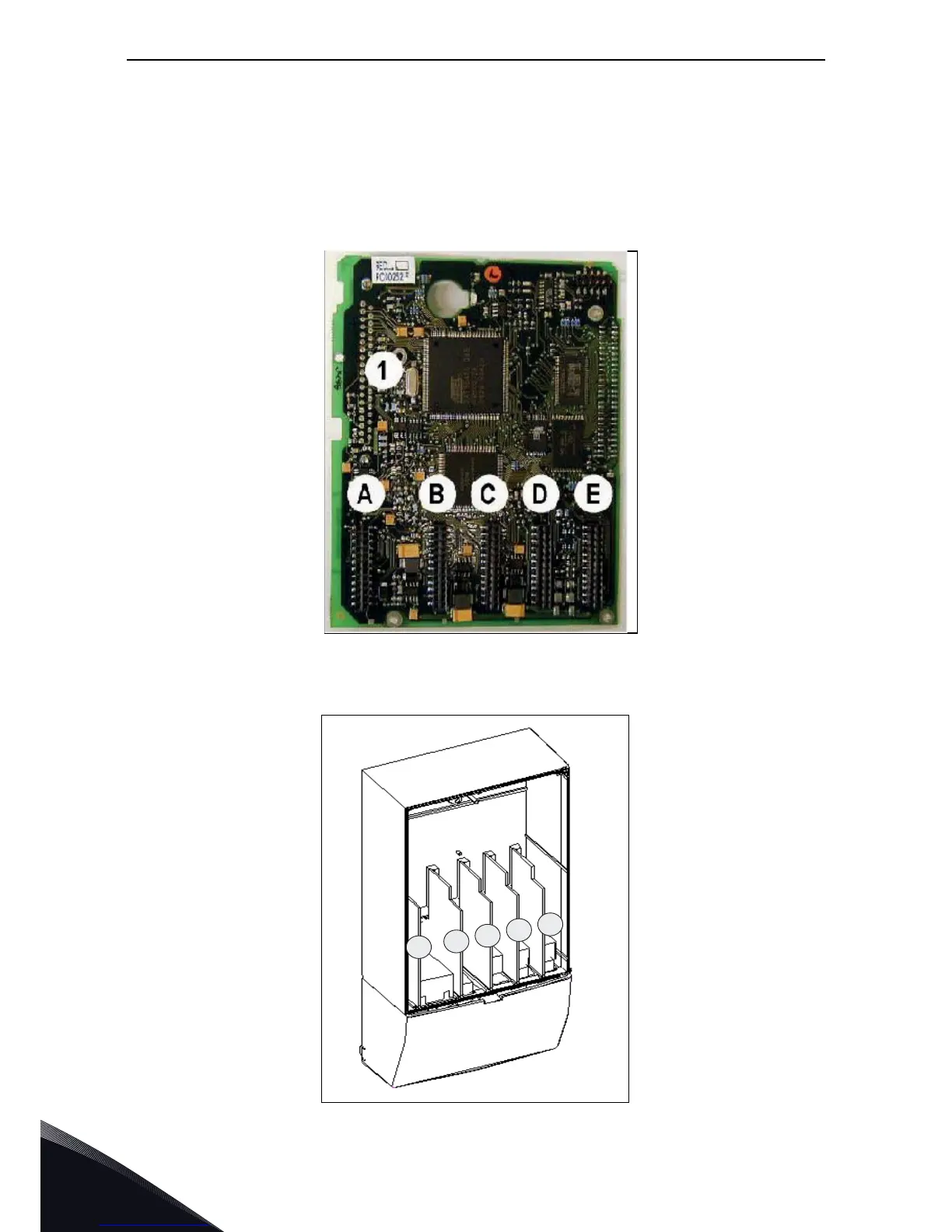
The control unit of VACON
®
NX Liquid-Cooled AC drive/inverter is installed into a mounting box. It
contains the control board and additional boards (see Figure 41 and Figure 42) connected to the five
slot connectors (A to E) of the control board. The control unit and the ASIC of the power unit are
connected through cables (and an adapter board). For more information, see page 108.
The mounting box with the control unit is mounted inside an enclosure. See the mounting
instructions on page 103.
Figure 41. VACON
®
NX control board
Figure 42. Basic and option board connections on the control board
11350_00
A
B
C
D
E
11351_00

Table of Contents

Other manuals for Vacon NX

Questions and Answers:

Question and Answer IconNeed help?

Do you have a question about the Vacon NX and is the answer not in the manual?

Vacon NX Specifications

General IconGeneral
Product TypeAC Drive
Control MethodScalar Control
EnclosureIP00, IP21
CommunicationEthernet
SafetySTO (Safe Torque Off)
Protection FeaturesOvercurrent, Overvoltage, Undervoltage, Overtemperature, Short Circuit
Ambient Temperature Range-10°C to +50°C (with derating above +40°C)
Cooling MethodAir-cooled, Liquid-cooled

Related product manuals