6
vacon • 106 Electrical cabling and connections
Local contacts: http://drives.danfoss.com/danfoss-drives/local-contacts/
6.3 Internal connections
As a general rule, all internal electrical and communications connections are made at the factory.
However, if modules have to be moved, for example, and the connections therefore removed, you will
have to re-establish the connections between 1) the Power Unit ASIC and the Driver Board(s) on the
one hand and 2) the Power Unit ASIC and the Optical Cable Adapter Board on the other.
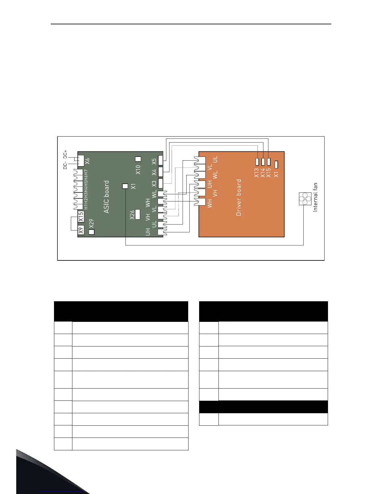
6.3.1 Connections between Power Unit ASIC and Driver Boards
See the figures and tables on the following pages for the correct connection of internal electrical
and communications connections.
NOTE! The minimum optical cable bending radius is 50 mm.
Figure 52. Terminals and connections between ASIC and driver board (CH61, CH62 and CH72)
Terminals on ASIC board
Gate driver signals from ASIC to driver
board
X9 Charge feedback UH Connect to UH on driver board
X15 Charging relay output UL Connect to UL on driver board
X6 Connect to DC-link on AC drive VH Connect to VH on driver board
X29 Flow supervision input VL Connect to VL on driver board
X26
Star Coupler terminal for drives greater
than CH61
WH Connect to WH on driver board
X10 +24 V supply voltage to control board WL Connect to WL on driver board
X3 Connect to terminal X13 on driver board
Terminal X1 on driver board
X4 Connect to terminal X14 on driver board X1 Connect to DC-link on AC drive
X5 Connect to terminal X15 on driver board
X1 Driver board fan power connection
11369_uk