11
vacon • 190 Non-regenerative front end
Local contacts: http://drives.danfoss.com/danfoss-drives/local-contacts/
11.13 Parameters
The parameters for software version ANCNQ100 are described below.
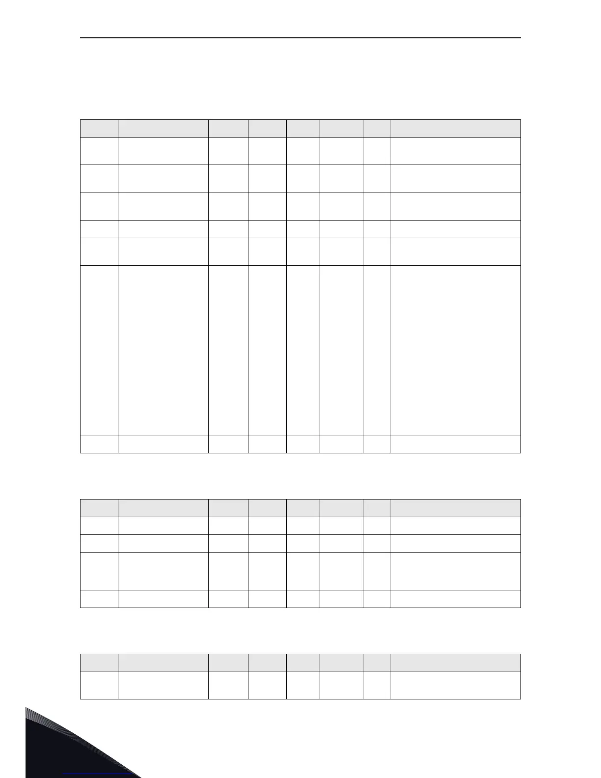
Table 83. Monitoring values
Code Parameter Min Max Unit Default ID Desciption
V1.2.1 DC Voltage 0 1500 V 0 7
DC voltage measured by external
AI devices
V1.2.2 Current 0 5000 A 0 3
Current measured by external AI
devices
V1.2.3 Unit Temperature -30.0 200.0 deg 0.0 8
Heatsink temp measured by
PT100 signal
V1.2.4 Choke Temp 1 -30.0 200.0 deg 0.0 50 Choke temp 1 measured by PT100
V1.2.5 Choke Temp 2 -30.0 200.0 deg 0.0 43
Choke temp 2 measured by
second PT100
V1.2.6 Status Word 0 65535 0 20
B0 =PrechargeReady
B1 =MC RUN
B2 =MC Warning
B3 =MC Fault
B4 =DIN Run
B5 =DIN BreakerFeedback
B6 =DIN MissInputPhase
B7 =DIN ChokeTempFault
B8 =DIN Reset
B9 =DOUT DC Precharging
B10=DOUT Close MCB
B11=DIN Cooling Fan
B12=DIN Cooling Fan2
Bit13=DIN External Fault Close
Bit14=DIN E Stop
Bit15=DIN Cooling OK
V1.2.7 Hour Counter 0 65535 Hour 0 1909 Run Hour counter
Table 84. Basic parameters G2.1
Code Parameter Min Max Unit Default ID Desciption
P2.1.1 Main Voltage 400 690 V 690 1910 Main supply voltage from network
P2.1.2 PreChargReadyLev 20 100 % 80 1911 Precharge ready level
P2.1.3 MaxChargeTime 0.00 30.00 s 5.00 1912
Max charge time. If the charging
time is more than this, a fault will
generated
P2.1.4 Password 0 65535 0 1913 Password
Table 85. Digital input G2.2.1
Code Parameter Min Max Unit Default ID Desciption
P2.2.1.1 Run 0 59 10 1915
Select Digital input signal for Run
command