Non-regenerative front end vacon • 191
Local contacts: http://drives.danfoss.com/danfoss-drives/local-contacts/
11
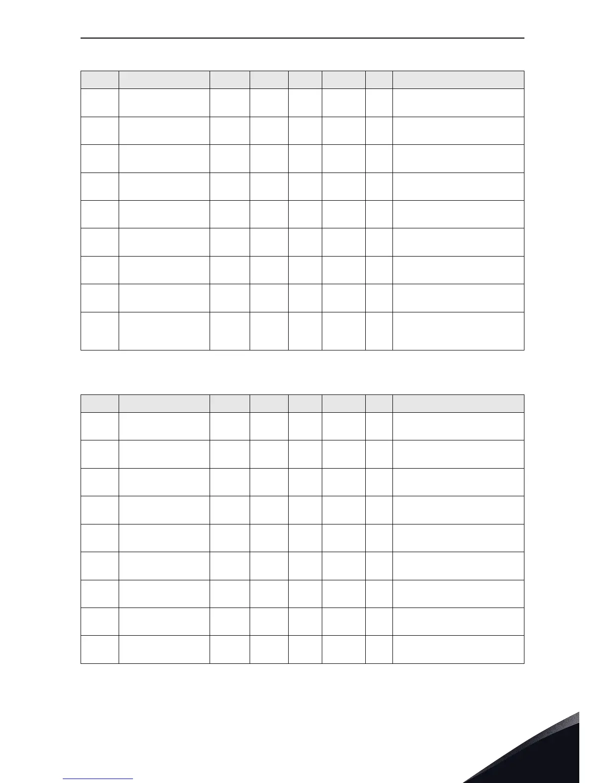
P2.2.1.2 BreakerFeedback 0 59 11 1916
Select digital input signal for
Breaker Feedback
P2.2.1.3 Miss Input Phase 0 59 12 1917
Select digital input for missing
input phase or low input voltage
P2.2.1.4 External Fault 0 59 13 1918
Select for digital input signal
external fault ,normal open logic
P2.2.1.5 Choke Temp 0 59 14 1919
Select for digital input Choke
Temp
P2.2.1.6 Fault Reset 0 59 15 1920
Select for digital input signal fault
reset
P2.2.1.7 E Stop 0 59 42 1921
Select for digital input signal E-
stop feedback
P2.2.1.8 Cooling OK 0 59 43 1922
Select for digital input signal
liquid cooling feedback
P2.2.1.9 Fan Sensor 1 0 59 44 1923
Select for digital input signal
cooling fan monitor
P2.2.1.1
0
Fan Sensor 2 0 59 45 1924
Selection of fan sensor2 from
digital input signal, default is from
OPT-B1 DIN.D5
Table 86. Analog input G2.2.2
Code Parameter Min Max Unit Default ID Desciption
P2.2.2.1 DC Voltage 0 59 10 1925
Selection for analog input of dc
voltage
P2.2.2.2 DC Min Point 0.00 40.00 % 20.00 1926
Percent value corresponds to 0 dc
voltage
P2.2.2.3 Max DC Voltage 500 2000 V 1500 1927
Dc voltage measurement devices
max range
P2.2.2.4 Current 0 59 11 1928
Selection of analog input signal
input current
P2.2.2.5 Current MinPoint 0.00 100.00 % 0.00 1929
Analog input signal min point for
current measurement
P2.2.2.6 Max Current 0 32000 A 1000 1930
Max current corresponds to max
analog input 100.00%
P2.2.2.7 Unit Temp 0 59 30 1931
Selection of analog input for
heatsink Temp
P2.2.2.8 Choke Temp 1 0 59 31 1932
Select analog input signal for
choke temp 1 from pt100 signal
P2.2.2.9 Choke Temp 2 0 59 32 1933
Select analog input signal for
choke temp 2 from PT100 signal
Table 85. Digital input G2.2.1
Code Parameter Min Max Unit Default ID Desciption