EasyManuals Logo

Vacon NX User Manual

Vacon NX
239 pages
To Next Page IconTo Next Page
To Previous Page IconTo Previous Page
Page #202 background imageLoading...
Page #202 background image
12
vacon • 200 Brake chopper unit (NXB)
Local contacts: http://drives.danfoss.com/danfoss-drives/local-contacts/
12.3.2 VACON
®
NXB topologies and connection
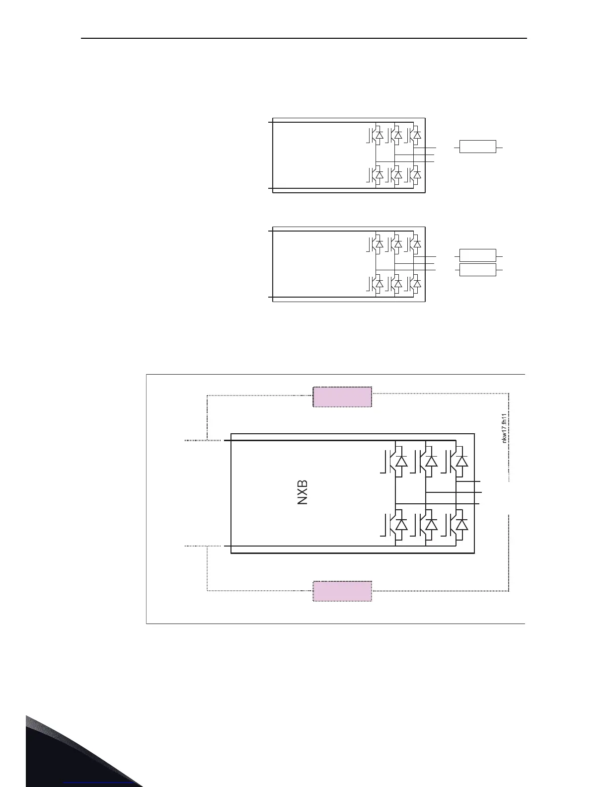
Figure 107. Brake chopper unit topology
Figure 108. VACON
®
Brake Chopper Unit connections
DC+
DC-
U/T1
V/T2
W/T3
Resistor DC+
DC+
DC-
U/L1
V/L2
Resistor DC+
Resistor DC-
W/L3
NXB (Brake Chopper Unit) + one resistor
is a braking power control unit.
Unnecessary energy is burnt off
NXB (Brake Chopper Unit) + two resistors
is a braking power control unit.
Unnecessary energy is burnt off
11403_uk
DC+
DC-
Resistor
Resistor
W/T3
U/T1
V/T2
11404_uk

Table of Contents

Other manuals for Vacon NX

Questions and Answers:

Question and Answer IconNeed help?

Do you have a question about the Vacon NX and is the answer not in the manual?

Vacon NX Specifications

General IconGeneral
Product TypeAC Drive
Control MethodScalar Control
EnclosureIP00, IP21
CommunicationEthernet
SafetySTO (Safe Torque Off)
Protection FeaturesOvercurrent, Overvoltage, Undervoltage, Overtemperature, Short Circuit
Ambient Temperature Range-10°C to +50°C (with derating above +40°C)
Cooling MethodAir-cooled, Liquid-cooled

Related product manuals