Electrical cabling and connections vacon • 109
Local contacts: http://drives.danfoss.com/danfoss-drives/local-contacts/
6
NOTE! Terminals X9 and X15 are connected by default. The cable can be removed if the signal is
receved from other source.
6.3.2 Connections between power unit ASIC and the control unit
The communication connections between the VACON
®
NX Liquid-Cooled drive power unit and the
control unit (see Chapter 6.2) can be established using either the conventional round cable
(standard in chassis CH3, CH4 and CH5) or optical cable (all chassis). Note that for chassis CH61
and greater, only optical cables can be used.
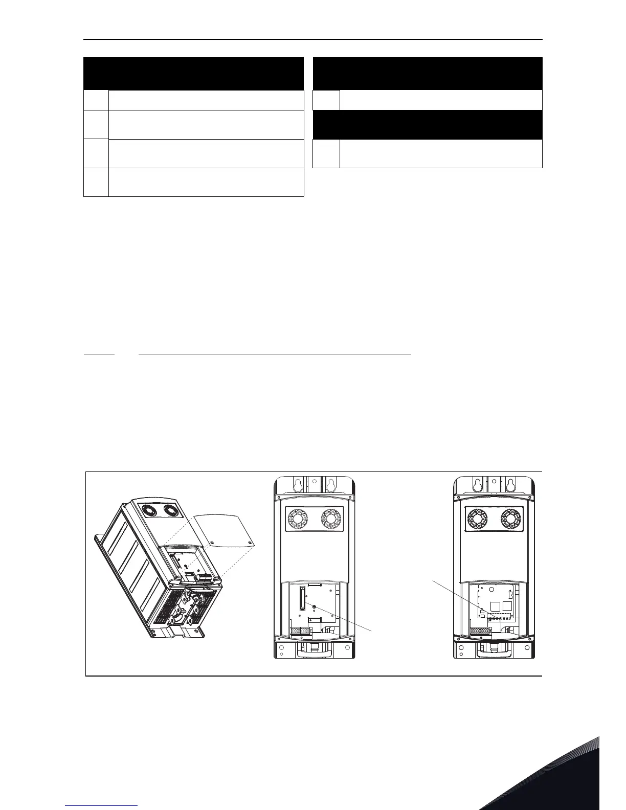
6.3.2.1
Connections with round cable (Chassis CH3, CH4 and CH5)
The communication connection between the drive power unit and the control unit in chassis CH3,
CH4 and CH5 are primarily made with conventional round cable and D-connectors at both ends.
Remove the protective cover to reveal the D-connector on the power unit. Connect the one end of
the communication cable to the D-connector of the power unit and the other end to the control unit.
If the Optical Cable Adapter Board (see below) sits on the D-connector of the control unit you have
to remove it first. See Figure 55 below.
Figure 55.
X10 +24 V supply voltage to control board WL Connect to WL on Phase W driver board
X3
Connect to terminal X1 on phase U driver
board
Terminal X2 on Phase driver board
X4
Connect to terminal X1 on phase V driver
board
X2 Internal fan power connection
X5
Connect to terminal X1 on phase W
driver board
Terminals on ASIC board
Gate driver signals from ASIC to driver
board