Electrical cabling and connections vacon • 91
Local contacts: http://drives.danfoss.com/danfoss-drives/local-contacts/
6
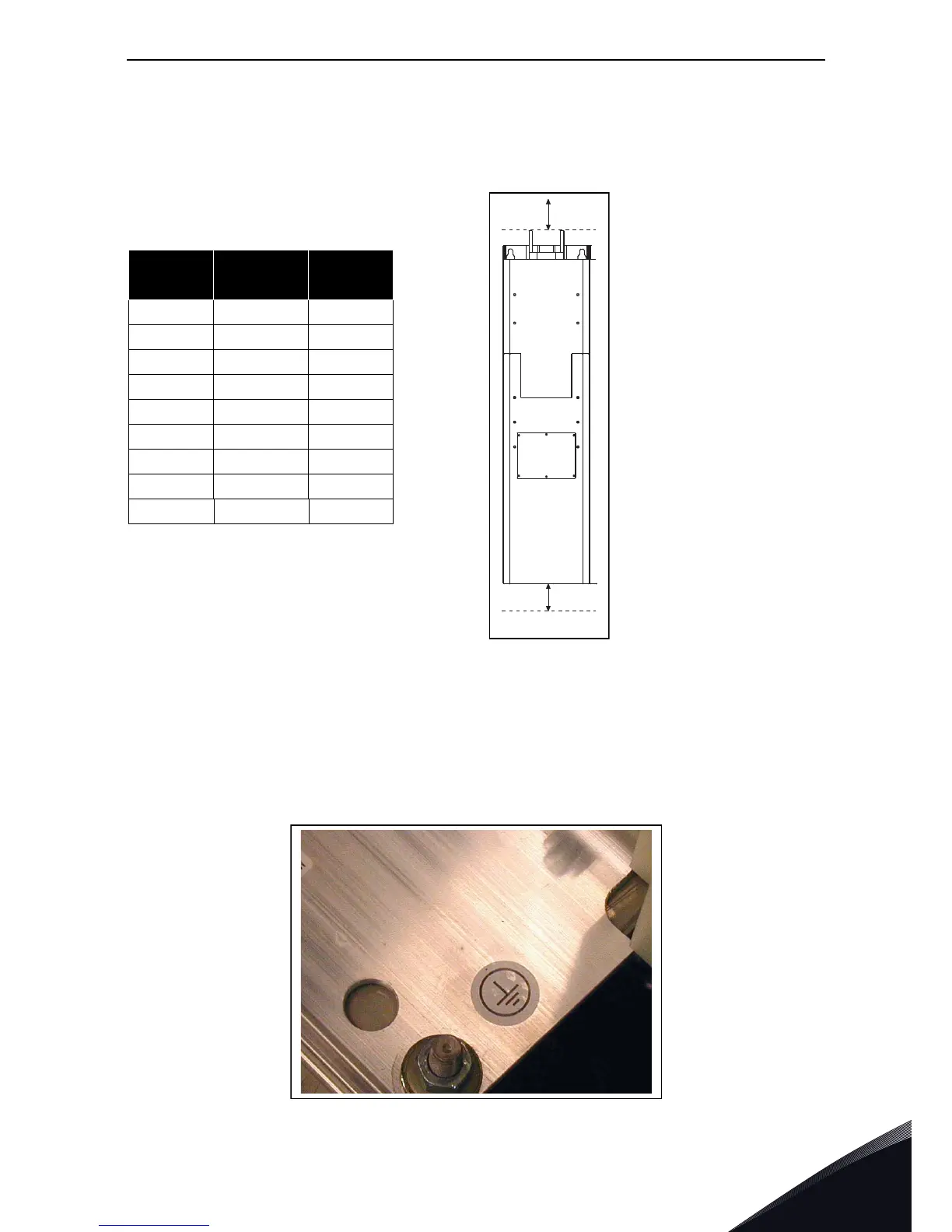
6.1.6 Installation space
Enough free space must be left above and below the AC drive/inverter to ensure practical and
appropriate electrical and cooling connections. The minimum dimensions are given in the table
below. The space left and right to the drive may be 0 mm.
6.1.7 Grounding of power unit
The mains cables are connected to the protective earth of the switchgear enclosure.
We recommend to connect the motor cables to the common PE of the cabinet/cabinet system.
For grounding of the drive itself, use the grounding terminal on the drive mounting plate (see
Figure 39) and tighten the grounding bolt to 13.5 Nm.
Figure 39. Grounding terminal on mounting plate
Table 45. Installation space
Chassis
A
[mm]
B
[mm]
CH3 100 150
CH4 100 200
CH5 100 200
CH61 100 300
CH62 100 400*
CH63 200 400*
CH64 200 500*
CH72 200 400*
CH74 200 500*
*Distance to the cable connection block.
Additional space must be reserved for
possibly used ferrite rings. See
Chapter 6.1.1.2.