10
vacon • 162 Active front end (NXA)
Local contacts: http://drives.danfoss.com/danfoss-drives/local-contacts/
10.6 Liquid-Cooled RLC filters
10.6.1 Introduction
VACON
®
Liquid-Cooled AFE units can be used with either Liquid Cooled or Air Cooled LCL filters.
The standard Liquid Cooled LCL filters are named RLC filter. The RLC filter type codes can be seen
from Table 62. The RLC filters are not included in the standard delivery of the AFE units and therefor
they need to be ordered reparately. More information about Air Cooled LCL filters can be found from
UD01190B, VACON
®
NX Active Front End User‘s Manual, FI9-13.
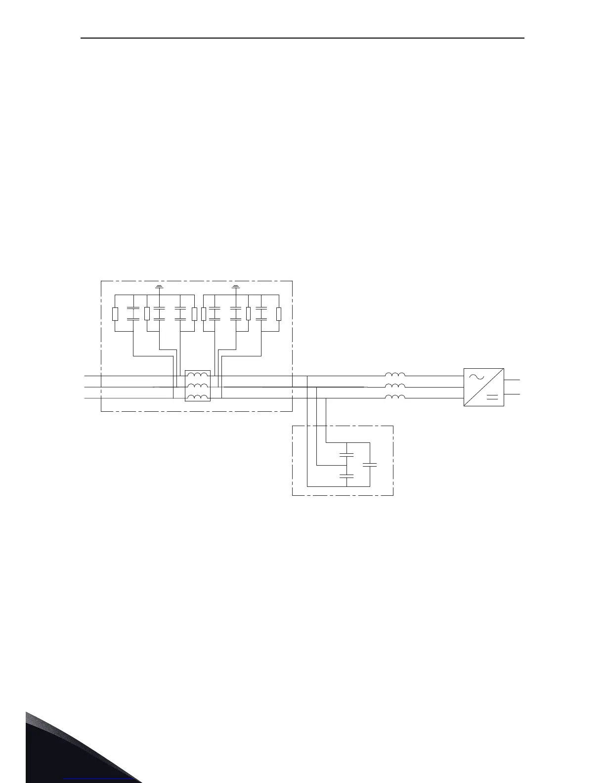
10.6.2 Wiring diagrams
The RLC filter contains a 3-phase chokes (L
net
)on the mains side, capacitors bank (C
bank
) and 3 pcs
of 1-phase choke (L
drive
) on the AFE side, Figure 87. The RLC also includes capacitors connected
against ground potential. There are resistors connected across the capacitors for discharging them
when the LCL filter is disconnected from the input power. The discharging resistors are 10 MΩ, 500
V and 0.5 W.
Figure 87. VACON
®
RLC filter wiring diagram